Applies To:
Show Versions
BIG-IQ Cloud
- 4.5.0, 4.4.0
Overview: Setting up an F5 Networks NVGRE gateway environment
This document provides instructions for installing the F5 Networks HNV Gateway PowerShell Module in the System Center Virtual Machine Manager (SCVMM) for integration into a Microsoft Hyper-V environment. The plug-in allows you to use a BIG-IP device or VE to act as a gateway between virtual networks in SCVMM and external networks. That is, with this plug-in, virtual machines can connect to the outside world, using NVGRE tunnels. After you have made this connection, you can configure the BIG-IP systems to provide application services for those virtual machines. The BIG-IQ system is the management endpoint for the BIG-IP systems. By default, all communication from the F5 Networks HNV Gateway PowerShell Module occurs through the BIG-IQ system.
About network virtualization using generic routing (NVGRE)
Using generic routing encapsulation (GRE) for policy-based, software-controlled network virtualization supports multitenancy in public and private clouds. NVGRE encapsulates Ethernet frames in an NVGRE-formatted GRE packet. You can combine virtual network segments managed by NVGRE with segments managed by VXLAN in either or both multicast and unicast modes.
NVGRE serves most data centers deploying network virtualization. The system encapsulates packets inside another packet, and the header of the new packet has the appropriate source and destination provider address (PA) IP address in addition to the virtual subnet ID (VSID), which is stored in the Key field of the GRE header. The VSID allows hosts to identify the customer's virtual machines for any given packet.
NVGRE is a policy-driven solution, so the provider addresses (PAs) and customer addresses (CAs) on the packets can overlap without problems. Consequently, all virtual machines on the same host can share a single PA.
These concepts are important for deploying NVGRE with Microsoft System Center Virtual Machine Manager (SCVMM):
- Customer address (CA)
- Provider address (PA)
- Virtual subnets
- Routing domains
- Logical networks
- IP pools for each logical network site
- Logical switches with port profiles
- Virtual port profiles
- VM networks
For additional information about network virtualization concepts, you can consult Microsoft documentation, for example: http://blogs.msdn.com/b/microsoft_press/archive/2014/03/24/ free-ebook-microsoft-system-center-network-virtualization-and-cloud-computing.aspx
About customer addresses
In NVGRE deployments with System Center Virtual Machine Manager (SCVMM), the customer address (CA) is the IP address assigned by the customer or tenant, based on the subnet, IP address range, and network topology. This IP address is visible only to the virtual machine and, eventually, other virtual machines within the same subnet VM network, if you allow routing.
In this example, ERICVM1 is a virtual machine currently running on Hyper-V host MTCPARIS-2. Its IPv4 address 192.168.0.2 is visible only to this virtual machine, and not to the underlying network fabric.
 Screen snippet showing visibility of customer address to VM
You can double-check this concept by connecting directly to the virtual machine, as in this example.
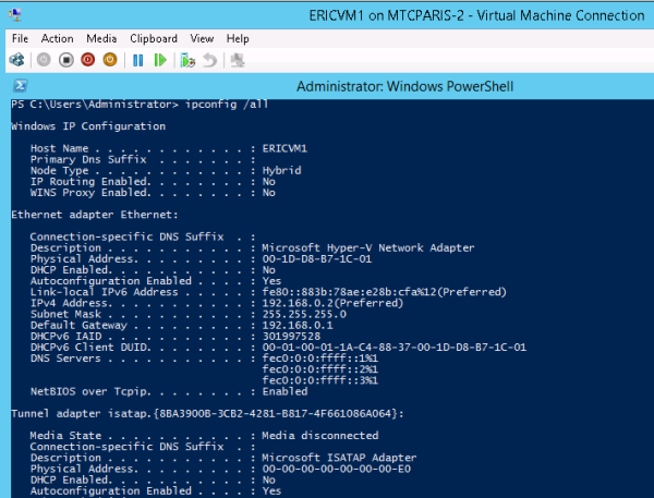 Command line verification of customer address visibility to VM
About provider addresses
In NVGRE deployments with System Center Virtual Machine Manager (SCVMM), the provider address (PA) is the IP address assigned by the administrator or by SCVMM, based on the physical network infrastructure. This IP address, visible only on the physical network, is used when Hyper-V hosts (either standalone or clustered) and other devices are exchanging packets, when participating in network virtualization.
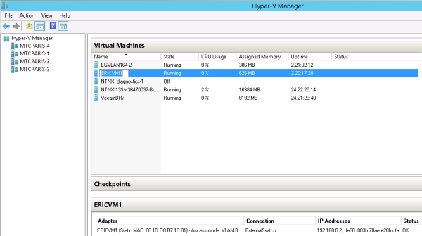
This example shows the virtual machines running on the Hyper-V host MTCPARIS-2, which includes the ERICVM1 virtual machine. The PA associated with the ERICVM1 virtual machine is 10.10.0.5, which is never visible to the ERICVM1 virtual machine itself.
 Example of provider address for VM participating in network virtualization
About virtual subnets
In NVGRE deployments with System Center Virtual Machine Manager (SCVMM), a unique virtual subnet ID (VSID) identifies an IP subnet at Layer 3 and a broadcast domain boundary at Layer 2, similar to VLAN technology. The VSID must be unique within the data center and within the range of 4096 to 2^24-2. Two customers in a hosted data center cannot both use the same VSID, even if they have different routing domains.
The VSID is a setting of the port of the virtual switch (vSwitch). However, it is presented to you as a property of the virtual network interface (VNI) of a VM.
In this example, the VSID for the ERICVM1 virtual machine is 7829576.
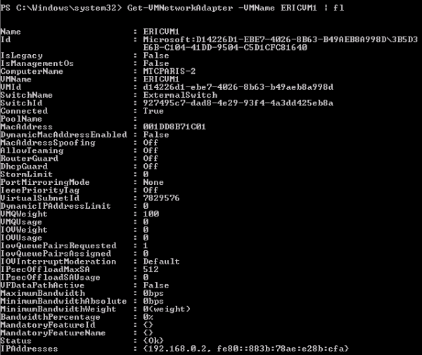 Example including VSID for a virtual machine
About routing domains
In NVGRE deployments with System Center Virtual Machine Manager (SCVMM), a routing domain defines a relationship between the virtual subnets created by the tenants, and identifies the VM network.
- The routing domain ID (RDID) has a globally unique ID (GUID) within the data center.
- The network vitualization stack enables Layer 3 routing between the subnets with a default gateway (always x.x.x.1), which cannot be disabled or configured.
- Hyper-V network virtualization (HNV) addresses distribute Layer-3 routing between virtualized subnets by including a network virtualization routing extension natively inside Hyper-V virtual switches running on each Hyper-V host.
- This distributed router can make cross-subnet routing decisions locally within the vSwitch to directly forward traffic between VMs on different virtualized subnets within the same virtual network or routing domain.
- To manage and distribute the appropriate routing policies to each Hyper-V host, System Center 2012 R2 VMM performs as the routing policy server, enabling the configuration of distributed routers across many Hyper-V hosts to be easily coordinated from a single, centralized point of administration.
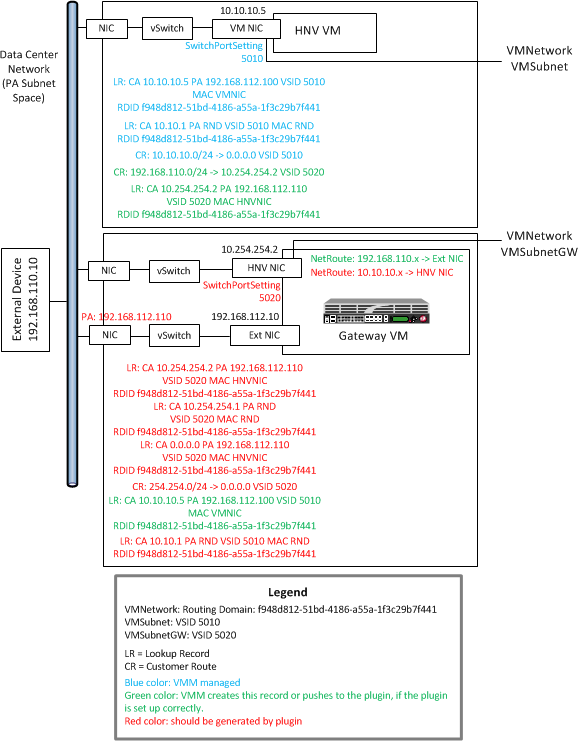
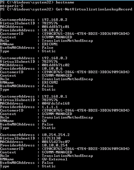
This example shows two different routing domains on the same Hyper-V host.
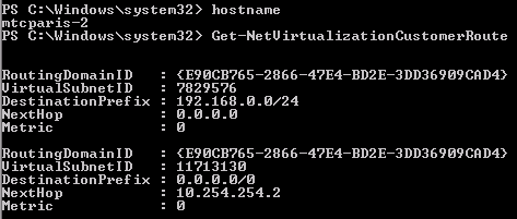 Example of two routing domains on a single Hyper-V host
About logical networks
In NVGRE deployments with System Center Virtual Machine Manager (SCVMM), a logical network can contain one or more associated network sites. A network site is a user-defined named grouping of IP subnets, VLANs, or IP subnet and VLAN pairs, which is used to organize and simplify network assignments. Logical networks are useful in large environments for mapping and streamlining network connectivity and dependencies in the configuration.
Uses for logical networks include but are not limited to these:
- Management: Contains the IP subnet used for management. Typically, both VMM and the Hyper-V servers are connected to this physical network. If you have more than one site and/or several VLANS, you can add all of these to the same logical network.
- Cluster: Contains the IP subnet and VLAN for cluster communication. Live Migration
- Front end: Contains the IP subnet used for public IP addresses.
- PA network: Contains the IP subnet used for provider addresses.
The logical network is dedicated to network virtualization. It is enabled at the logical network level. This network must be isolated. Do not use any of the other networks for this puspose.
The logical network in this example has an associated IP pool, so that SCVMM can manage IP address assignments to the hosts dedicated to network virtualization, the virtualization gateway VMs, and the virtualization hosts running virtual machines connected to VM networks.
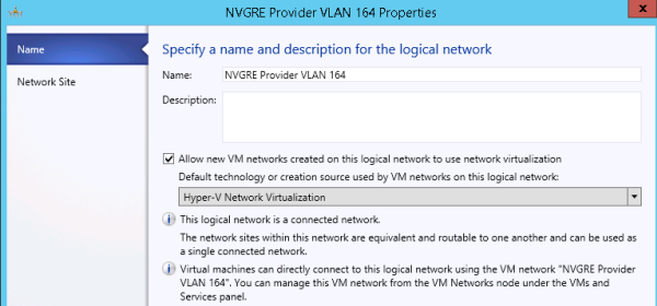 Specifying a logical network
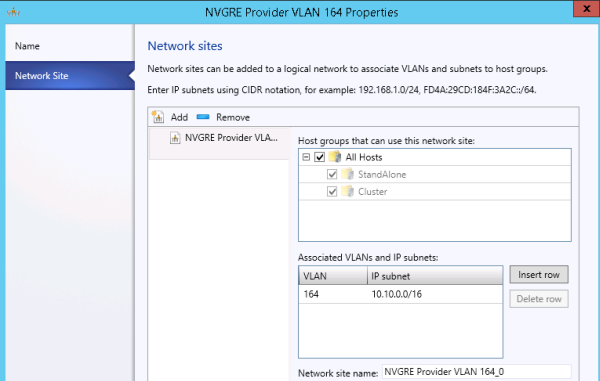 Adding network sites to a logical network
About IP address pools
In NVGRE deployments with System Center Virtual Machine Manager (SCVMM), You must have IP address pools for each logical network site, so that VMM can assign the right IP configuration to its resources within this network.
In these configuration screen examples, note that there is no direct mapping of the PA network to the hosts. The PA network is available to the hosts only through this configuration, together with Uplink port profiles and logical switches.
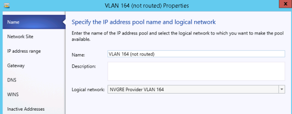 Specifying the IP address pool name and logical network
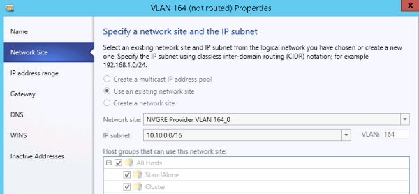 Specifying a network site and the IP subnet
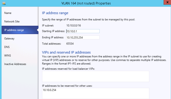 Specifying the range of IP addresses for a pool
About logical switches with port profiles
In NVGRE deployments with System Center Virtual Machine Manager (SCVMM), you can use port profiles and logical switches to create identical capabilities for network adapters across multiple hosts. Port profiles and logical switches act as containers for the properties or capabilities that you want your network adapters to have. Instead of configuring individual properties or capabilities for each network adapter, you can specify the capabilities in port profiles and logical switches, and then apply these capabilities to the appropriate adapters. This can simplify the configuration process and ensure that your hosts are using correct load balancing algorithm and the virtual adapters have the right settings related to capabilities and QoS.
About virtual port profiles
In NVGRE deployments with System Center Virtual Machine Manager (SCVMM), you can take advantage of several port profiles that are shipped with SCVMM and use the existing profiles for host management, cluster, and live migration.
You can see the profiles in SCVMM by navigating to Port Profiles on the networking tab in Fabric.
For example, on the Security Settings screen, you can enable Allow guest specified IP addresses, so that VMM can detect changes made to tenants within the guests, and update the NVGRE policy in the environment.
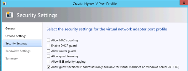 Setting security for a virtual port profile
About VM networks
You need to create VM networks with 1:1 mapping to your logical networks in the fabric.
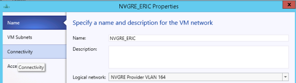 Creating a VM network
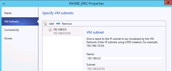 Specifying VM subnets
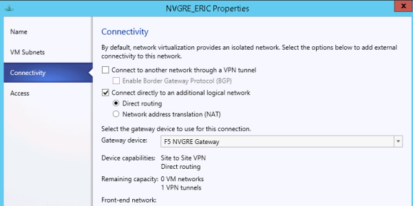 Adding external connectivity to a VM network
Before you begin the installation
Before you install the F5 Networks HNV Gateway PowerShell Module, you need to prepare the BIG-IP system. F5 Networks strongly recommends using Engineering Hotfix 121.14 for v11.5.1-HF2. It includes bug fixes that ensure that monitors on VIPs work correctly in an HA setup that also uses tunnels.
Make sure that the BIG-IP system is configured with these considerations in mind.
- At least one BIG-IP system is configured with at least one IP address, preferably on the management interface.
- Verify that at least one VLAN has connectivity to the provider network.
When you configure the SCVMM gateway using a config file, you specify the following BIG-IQ parameters:
- The IP address of the F5 BIG-IQ system
- The name of a BIG-IQ device resolver group that contains either one standalone BIG-IP system or two BIG-IP systems in a device cluster
For a standalone BIG-IP system
If you are setting up a standalone BIG-IP system, verify that you have not configured a masquerading MAC address.
For a pair of BIG-IP systems in a device group
If you are setting up a pair of BIG-IP devices as a device group, verify the following.
- You are using a Sync-Failover device group.
- Auto-Sync and Network Failover are turned on for the device group.
- You have configured a masquerading MAC address.
- Make a note of the traffic group used for floating objects; you need to provide it in the configuration file.
When you are not using route domains
When you do not use route domains; that is, when UseRouteDomains is set to false in the F5 Networks HNV Gateway PowerShell Module configuration file, you must create a forwarding virtual server on each of your BIG-IP systems.
Here is an example using the tmsh command line utility.
create ltm virtual scvmm-vs destination 0.0.0.0:0 mask any ip-forward source-address-translation { type automap }Additional information
The following files are shipped with the plug-in.
- Plug-in binaries: C:\Windows\System32\WindowsPowerShell\v1.0\Modules\F5GatewayProvider
- Sample configuration file for one BIG-IP system:C:\Windows\System32\WindowsPowerShell\v1.0\Modules\F5GatewayProvider\gateway-one-bigip.cfg
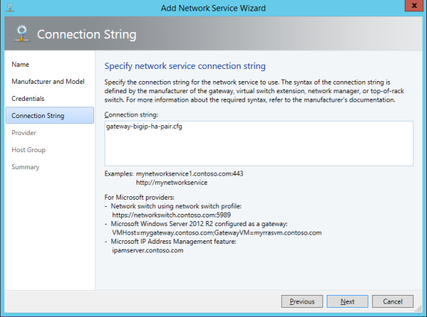
- Sample configuration file for two BIG-IP systems in a redundant (HA) pair:C:\Windows\System32\WindowsPowerShell\v1.0\Modules\F5GatewayProvider\gateway-bigip-ha-pair.cfg
- Script to create a BIG-IQ device resolver group:C:\Windows\System32\WindowsPowerShell\v1.0\Modules\F5GatewayProvider\Setup-Device-Group.ps1
- Log file:C:\Program Files\Microsoft System Center 2012 R2\Virtual Machine Manager\bin\F5-SCVMM-Gateway.log
Task summary
Before you start this installation, you need to acquire the file F5GatewayPowerShellSetup.msi, which you can find on the BIG-IQ system. You must use an account with administrative privileges to complete the installation. Ensure that the BIG-IP system includes a local IP address in the provider IP address space, and make a note of this address. Also, ensure that the network interface (NIC) to be used for the provider addresses is named WNVNIC.
Task list
Creating the BIG-IQ device resolver group
Installing the F5 Networks HNV Gateway PowerShell Module
-
Run the file F5GatewayPowerShellSetup.msi.
-
After the installation has completed, restart the SCVMM.

Configuring the VM gateway BIG-IP system to forward packets
- Create an external VLAN on the BIG-IP system that has external access.
- Create a default route on the BIG-IP system that directs traffic outward.
Configuring the F5 gateway in SCVMM
-
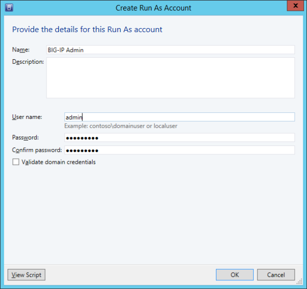
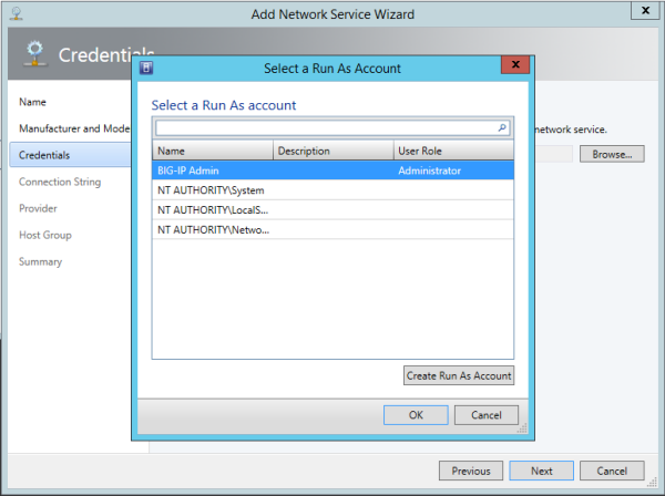
In the VMM's Settings area, create a new Run As account. This account includes
the user name and password of the BIG-IP system you are using. It does not use
domain credentials. You will select this Run As account later in the
configuration process. If you already have an appropriate Run As account, you do
not need to create another. Multiple gateways can refer to the same Run As
account.
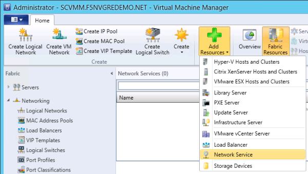
-
In the Fabric portion of the user interface, click Add
Resources, and select Network Service, as
shown.
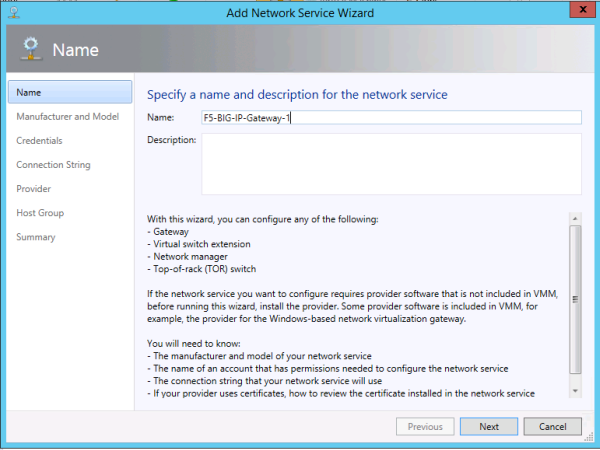
-
Type a name for the gateway, as shown, and then click
Next.
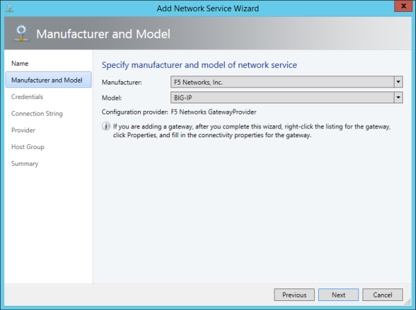
-
For the Manufacturer, select F5 Networks,
Inc., and for the Model, select
BIG-IP, as shown, and then click
Next.
-
Select the Run As account you created previously, and then click
OK.
-
Specify the connection string for the gateway.
This is the name of the configuration file you edited and saved.
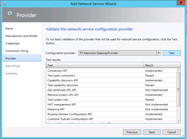
-
Click Test to test the gateway.
SCVMM exercises the gateway functions, as shown in this example. Only some of the network service functionality will be implemented.
-
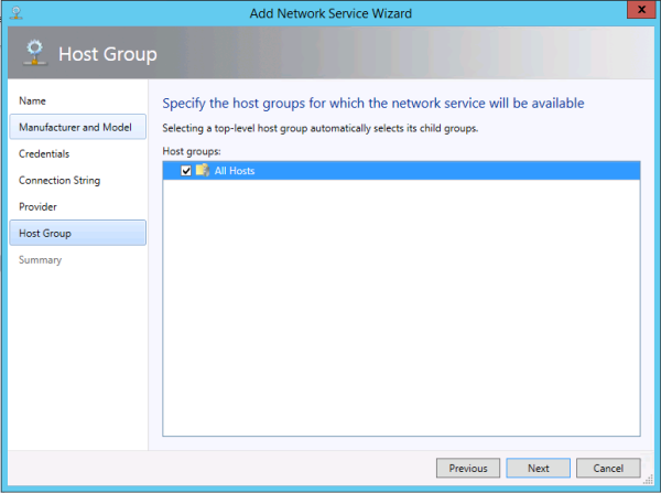
Select a host group for the plug-in, as shown.
-
Confirm the settings you configured, as shown in this example, and then click
Finish.
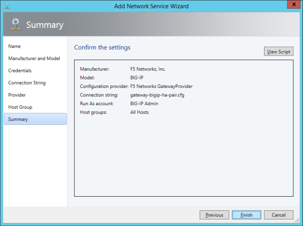 The SCVMM performs an initial configuration of the BIG-IP system. This
might take a few seconds.
The SCVMM performs an initial configuration of the BIG-IP system. This
might take a few seconds.
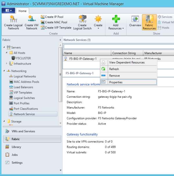
-
Right-click the gateway you created, and select
Properties, as shown.
-
In the left navigation pane, select Connectivity, and specify the front end and
back end SCVMM interfaces on the BIG-IP system, as shown, and then click
OK.
Although the front end connection does not matter to the gateway plug-in, you must select one. For the back end connection, select the BIG-IP VLAN that has connectivity on the SCVMM provider network. Note that the BIG-IP system will be configured with a self IP address on this network, using a dynamically allocated address.
The gateway you created is now ready to use.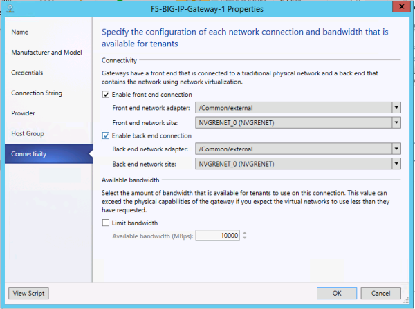
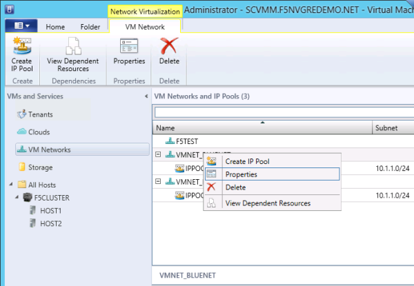
-
In the VM Network tab, right-click the VM network on which you want the BIG-IP
system to provide gateway services, and select
Properties, as shown.
-
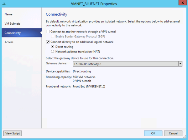
In the left navigation pane, select Connectivity, select the check box
Connect directly to an additional logical network,
and then select the gateway you created, as shown.