Updated Date: 07/07/2026
Environmental Guidelines
The F5 r5000/r10000/r12000 Series platform is an industrial network appliance that is designed to be mounted in a standard 19-inch EIA rack.
Follow these guidelines to adhere to safety precautions:
- Install the rack according to the manufacturer’s instructions and check the rack for stability before placing equipment in it.
- Build and position the rack so that after you install the platform, the power supply and the vents on both the front and back of the unit remain unobstructed. The platform must have adequate ventilation around the unit at all times.
- Although not required, a 1U space between units makes it easier for you to remove the unit from the rack in the event that the unit requires service. A 1U space between units also provides additional cable routing options.
- Leaving at least 100 mm of space from the front panel of the unit to the rack front or rack door provides enough room for you to route the cables without excessive bending or insulation damage.
- Do not plug the unit into a branch circuit shared by more electronic equipment than the circuit is designed to manage safely at one time.
- Route and secure power cords so that they do not obstruct removal of the fan tray.
This device might accept optics containing a laser that is classified as a Class 1 Laser Product in accordance with U.S. FDA regulations and the IEC 60825-1. The product does not emit hazardous laser radiation.
The product complies with 21 CFR 1040.10 and 1040.11 (except for deviations pursuant to Laser Notice No. 50, dated June 24, 2007) and with IEC 60825-1.
Warning: Use of controls or adjustments or performance of procedures other than those specified herein or in the laser product’s installation guide may result in hazardous radiation exposure. To reduce the risk of exposure to hazardous radiation:
- Do not try to open the module enclosure. There are no user-serviceable components inside.
- Do not operate controls, make adjustments, or perform procedures to the laser device other than those specified herein.
- Allow only Authorized Service technicians to repair the unit.
Important: This product is sensitive to electrostatic discharge (ESD). F5 recommends that you use proper ESD grounding procedures and equipment when you install or maintain the unit.
CAUTION:
Customers should not attempt to replace batteries. There is a risk of explosion if a battery is replaced with an incorrect type. Field technicians should dispose of used batteries according to the instructions.
Avertissement : Il y à risque d’explosion si la batterie est remplacée par une batterie de type incorrect. Mettre au rebut les batteries usagées conformément aux instructions.
Note: Suitable for installation in Information Technology Rooms in accordance with Article 645 of the National Electrical Code and NFPA 75.
Suitable for installation in Network Telecommunication Facilities.
Suitable for installation in Outside Plant (OSP).
Warning: The intra-building ports of the equipment or subassembly are suitable for connection to intra-building or unexposed wiring or cabling only. The intra-building ports of the equipment or subassembly MUST NOT be metallically connected to interfaces that connect to the OSP or its wiring. These interfaces are designed for use as intra-building interfaces only (Type 4 or 4a ports as described in GR-1089-CORE) and require isolation from the exposed OSP cabling. The addition of Primary Protectors is not sufficient protection in order to connect these interfaces metallically to OSP wiring.
Remarque : Peut être installé dans des salles de matériel de traitement de l’information conformément à l’article 645 du National Electrical Code et à la NFPA 75.
Note: If installed in a closed or multi-unit rack assembly, the operating ambient temperature of the rack environment may be greater than room ambient. Therefore, consideration should be given to installing the equipment in an environment compatible with the maximum ambient temperature (Tma) specified by the manufacturer.
Note: Installation of the equipment in a rack should be such that the amount of air flow required for safe operation of the equipment is not compromised.
Note: Mounting of the equipment in the rack should be such that a hazardous condition is not achieved due to uneven mechanical loading.
Note: Consideration should be given to the connection of the equipment to the supply circuit and the effect that overloading of the circuits might have on overcurrent protection and supply wiring. Appropriate consideration of equipment nameplate ratings should be used when addressing this concern.
Note: Reliable earthing of rack-mounted equipment should be maintained. Particular attention should be given to supply connections other than direct connections to the branch circuit (e.g. use of power strips).
The r5000/r10000/r12000 Series platforms ship with a rack mount kit to help install the system more easily. This kit requires that the rack or cabinet has certain clearances and spacing, as shown here.
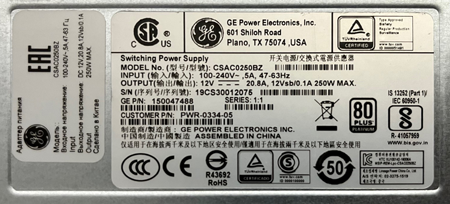
All rSeries platforms support either single or dual power supply units (PSUs). When your system includes dual PSUs, both supplies must be of the same type. To verify this, make sure that the supplies have matching base part numbers (PWR-XXXX). You can find the base part number printed on the label on top of the individual PSU.
Note: The full part number is a nine digit number (PWR-XXXX-YY). The base part number is seven digits and must match, but the suffix (-YY) does not need to match.
If you cannot read the base part number, ensure that the pull handles are both in a vertical orientation and that the sheet metal on the power cord face for each supply has the same perforation shapes.
When you add or replace a PSU in your system, be sure to verify the supply’s features and that the PWR-XXXX part numbers match to ensure that you have the correct supply.
F5 rSeries platforms support these power supply units (PSUs), depending on power configuration.
r2000/r4000 Series
| PSU type | Wattage | Part number | Pull handle description | Power cord face description |
|---|---|---|---|---|
| AC | 250W | PWR-0334-xx | Black-colored horizontal pull handle | Silver-colored power cord face with hexagon-shaped perforations |
| HVDC | 650W | PWR-0378-xx | Black-colored vertical pull handle | Silver-colored power cord face with rectangle-shaped perforations |
| DC | 650W | PWR-0307-xx |
An AC-powered installation must meet these requirements:
- Use a 15 amp external branch circuit protection device to install the unit.
- Use one power feed for each individual power supply.
Important: The platform must be installed in a RESTRICTED ACCESS LOCATION, such as a central office or customer premises environment.
Note: The power cables included with this unit are for exclusive use with this unit and should not be used with other electrical appliances.
製品には、同梱された電源コードセットを使用すること及び同梱された電源コー ドセットは、他の製品に使用しないこと.
Note: These guidelines apply to STATIONARY PLUGGABLE EQUIPMENT TYPE A with simultaneous multiple connections to the AC MAINS SUPPLY:
- The building installation shall provide a means for connection to protective earth; and
- The equipment is to be connected to that means; and
- A SERVICE PERSON shall check whether or not the socket-outlet from which the equipment is to be powered provides a connection to the building protective earth. If not, the SERVICE PERSON shall arrange for the installation of a PROTECTIVE EARTHING CONDUCTOR from the separate protective earthing terminal to the protective earth wire in the building.
CAUTION:
High leakage current. Earth connection essential before connecting supply.
A DC-powered installation must meet these requirements:
- Use a 15 amp external branch circuit protection device to install the unit.
- For permanently connected equipment, incorporate a readily accessible disconnect in the fixed wiring.
- Use only copper conductors.
- Cabling for the system must be grounded on both sides.
- Use one power feed for each individual power supply.
Note: The battery return terminals on the DC-powered platform are in an isolated DC return (DC-I) configuration.
CAUTION:
Install DC-powered equipment only in restricted access areas, such as dedicated equipment rooms, equipment closets, or similar locations.
ATTENTION :
Installer le matérial alimenté par courant continu uniquement dans des zones à accès reglementé, telles que des salles de matériel, des armoires de materiel ou tout emplacement similaire.
CAUTION:
This equipment has a connection between the earthed conductor of the d.c. supply circuit and the earthing conductor. All of the following installation conditions must be met:
- This equipment shall be connected directly to the d.c. supply system earthing electrode conductor or to a bonding jumper from an earthing terminal bar or bus to which the d.c. supply system earthing electrode conductor is connected.
- This equipment shall be located in the same immediate area (such as adjacent cabinets) as any other equipment that has a connection between the earthed conductor of the same d.c. supply circuit and the earthing conductor, and also the point of earthing of the d.c. system. The d.c. system shall not be earthed elsewhere.
- The d.c. supply source shall be located within the same premises as this equipment.
- Switching or disconnecting devices shall not be in the earthed circuit conductor between the d.c. source and the point of the connection of the earthing electrode conductor.
ATTENTION :
Ce matériel doit être raccordé directement au conducteur de la prise de terre du circuit d’alimentation c.c. ou à une tresse de mise à la masse reliée à une barre omnibus de terre laquelle est raccordée à l’électrode de terre du circuit d’alimentation c.c.
- Les appareils dont les conducteurs de terre respectifs sont raccordés au conducteur de terre du même circuit d’alimentation c.c. doivent être installés à proximité les uns des autres (p.ex., dans des armoires adjacentes) et à proximité de la prise de terre du circuit d’alimentation c.c.
- Le circuit d’alimentation c.c. ne doit comporter aucune autre prise de terre.
- La source d’alimentation du circuit c.c. doit être située dans la même pièce que le matériel.
- Il ne doit y avoir aucun dispositif de commutation ou de sectionnement entre le point de raccordement au conducteur de la source d’alimentation c.c. et le point de raccordement à la prise de terre.
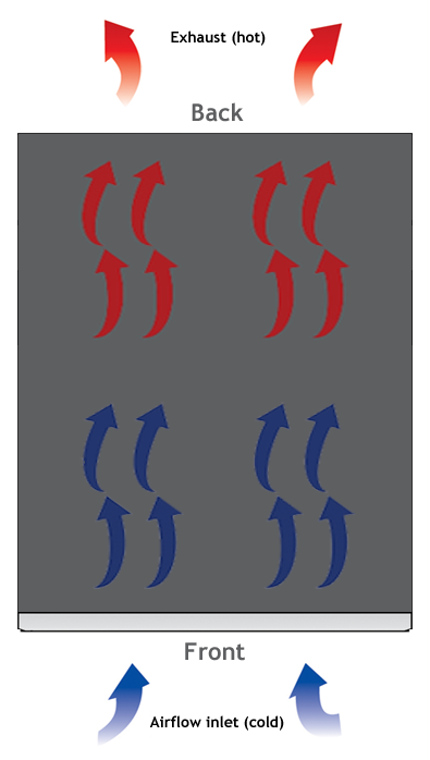
When you install the platform into a rack, it is important to understand the unit’s airflow direction so that you can ensure proper cooling.
The platform employs a negative pressure fan system, which draws cold air in from the front of the chassis.