Updated Date: 07/09/2026
Platform Overview
F5 r5000/r10000/r12000 Series platforms are powerful systems that are designed specifically for application delivery performance and scalability.
The F5 r5000 Series platforms are available with either an AC, a standard DC, or a high-voltage DC (HVDC) configuration. HVDC power supply units (PSUs) are available as a field-installed upgrade option (part number PWR-0378-xx) only on r5000 Series platforms with a part number of 200-0411-xx.
The F5 r10000/r12000 Series platforms are available with either an AC, a standard DC, or a high-voltage DC (HVDC) configuration. HVDC power supply units (PSUs) are available as a field-installed upgrade option (part number PWR-0384-xx) only on r10000/r12000 Series platforms with a part number of 200-0413-xx.
The F5 r5000 (part number 203-0464-xx) and r10000 (part number of 203-0463-xx) Series platforms with either an AC, a standard DC, or a high-voltage DC (HVDC) configuration available and support only F5OS-A 1.8.4 or later software versions.
Warning: High-voltage DC (HVDC) power supply units (PSUs) are specially designed to operate at a DC voltage range from 180VDC to 400VDC, and they are NOT compatible with standard DC PSUs that operate from -44VDC to -72VDC. DO NOT attempt to install an HVDC PSU for standard DC PSU operations OR mix HVDC PSUs and DC PSUs in the same unit.
The F5 r5000 (r5000-DF) and r10000 (r10000-DF) Series platforms are available with a FIPS-validated hardware security module (HSM) as a factory-installed option. These platforms have dual solid-state drives (SSDs). For more information on managing FIPS platforms, see F5 Platforms: FIPS Administration at Documentation - F5OS-A and F5 rSeries.
| Platform | Part number | F5OS-A supported versions | Supported tenant software versions (BIG-IP) |
|---|---|---|---|
| r5000 | 200-0411-xx | v1.5.x, v1.8.0 and later | v17.0 and later |
| r5000 | 203-0464-xx | v1.8.4 and later | v17.1 and later |
| r10000/r12000S | 200-0413-xx | v1.5.x, v1.8.0 and later | v17.0 and later |
| r10000 | 203-0463-xx | v1.8.4 and later | v17.1 and later |
Note: Verify the part number of your platform by logging in to the CLI of the system and typing this command:
-
Connect to the system using a management console or console server. The default baud rate and serial port configuration is 19200/8-N-1.
-
Log in to the command line interface (CLI) of the system using an account with admin access.
When you log in to the system, you are in user (operational) mode.
-
View the part number of your platform:
show components component platform stateA summary to this example displays: In this example the new revision for the platform r5000 is displayed:
appliance-1# show components component platform state
state description    r5900
state serial-no      f5-tynv-itdy
state part-no        "203-0464-00 REV B"
state empty          false
state tpm-integrity-status Valid
state memory total    134725894144
state memory available 9439006720
state memory free     5881118720
state memory used-percent 93
state memory platform-total 16106782720
state memory platform-used 6272737280
state memory platform-used-percent 38
state temperature current 17.8
state temperature average 18.1
state temperature minimum 17.8
state temperature maximum 18.7
                                                                                        USED
AREA                          CATEGORY           TOTAL         FREE          USED         PERCENT
---------------------------------------------------------------------------------------------------
platform/sysroot              F5OS System        111606771712  83976163328   21937680384  20
platform/big-ip-tenant-disks  F5OS Tenant Disks  459252056064  435822940160  76701696     0
platform/images
In this example the old revision for the platform r5000 is displayed:
appliance-1# show components component platform state
state description    r5900
state serial-no      f5-oqhv-lkbc
state part-no        "203-0411-05 REV B"
state empty          false
state tpm-integrity-status Unavailable
state memory total    134725898240
state memory available 9734971392
state memory free     5664395264
state memory used-percent 92
state memory platform-total 16106786816
state memory platform-used 5964849152
state memory platform-used-percent 37
state temperature current 24.7
state temperature average 24.2
state temperature minimum 23.3
state temperature maximum 24.9
                                                                                        USED
AREA                          CATEGORY           TOTAL         FREE          USED         PERCENT
---------------------------------------------------------------------------------------------------
platform/sysroot              F5OS System        111606771712  83369607168   22544236544  21
platform/big-ip-tenant-disks  F5OS Tenant Disks  459252056064  428182343680  7717298176   1
tenant/bigiptenant9           BIG-IP Tenant      152471339008  144830750720  7640588288   5
tenant/defaultbip-1           BIG-IP Tenant      152471339008  145197432832  7273906176   4
platform/images               F5OS Images        114710360064  92504252416   16355475456  15
For more information, please see the data sheet at www.f5.com/services/resources/datasheets.
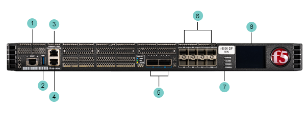
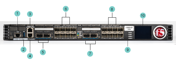
Before you install your F5 rSeries platform, review information about the controls and ports located on both the front and back of the platform.
On the front of the platform, you can use the LCD touchscreen to view information about, manage, and reset the system. You can also use the front-panel LEDs to assess the condition of the system.

- 1000-BaseT capable management port
- USB 3.0 port
- Serial console port
- Serial failover port *
- 100G/40G QSFP+/QSFP28 ports (2)
- 25G/10G SFP28/SFP+ ports (8)
- Indicator LEDs
- 2.2 inch LCD touchscreen
- 1000-BaseT capable management port
- USB 3.0 port
- Serial console port
- Serial failover port *
- 100G/40G QSFP+/QSFP28 ports (2)
- 25G/10G SFP28/SFP+ ports (8)
- Indicator LEDs
- 2.2 inch LCD touchscreen
- 1000-BaseT capable management port
- USB 3.0 port
- Serial console port
- Serial failover port *
- 100G/40G QSFP28/QSFP+ ports (2)
- 25G/10G SFP28/SFP+ ports (8)
- 100G/40G QSFP28/QSFP+ ports (2)
- 25G/10G SFP28/SFP+ ports (8)
- Indicator LEDs
- 2.2 inch LCD touchscreen
- 1000-BaseT capable management port
- USB 3.0 port
- Serial console port
- Serial failover port *
- 100G/40G QSFP28/QSFP+ ports (2)
- 25G/10G SFP28/SFP+ ports (8)
- 100G/40G QSFP28/QSFP+ ports (2)
- 25G/10G SFP28/SFP+ ports (8)
- Indicator LEDs
- 2.2 inch LCD touchscreen

- 1000-BaseT capable management port
- USB 3.0 port
- Serial console port
- Serial failover port *
- 100G/40G QSFP28/QSFP+ ports (2)
- 25G/10G SFP28/SFP+ ports (8)
- 100G/40G QSFP28/QSFP+ ports (2)
- 25G/10G SFP28/SFP+ ports (8)
- Indicator LEDs
- 2.2 inch LCD touchscreen
Note: * Serial (hardwired) failover is not supported by the F5OS-A software layer. If high availability (HA) failover is required, configure network failover between BIG-IP tenants.
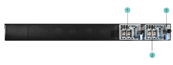
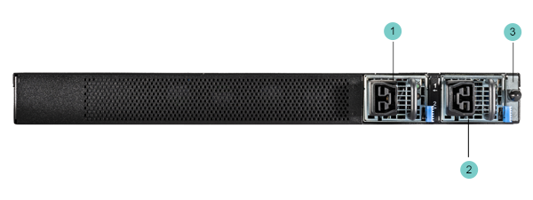
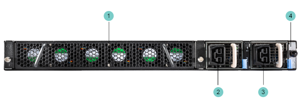
The back of the r5000 Series platform includes one power supply unit (PSU), one power blank, and a chassis ground terminal. The dual PSU option is shown below.
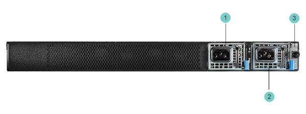
- Power input panel 1 (AC power receptacle)
- Power input panel 2 (AC power receptacle)
- Chassis ground terminal
- Power input panel 1 (DC terminal)
- Power input panel 1 (DC terminal)
- Chassis ground terminal
- Power input panel 1 (HVDC power receptacle)
- Power input panel 2 (HVDC power receptacle)
- Chassis ground terminal
The back of the r10000/r12000 Series platform includes a removable fan tray, two power supply units (PSUs), and a chassis ground terminal.
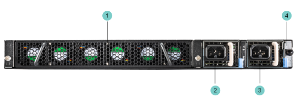
- Fan tray (removable)
- Power input panel 1 (AC power receptacle)
- Power input panel 2 (AC power receptacle)
- Chassis ground terminal
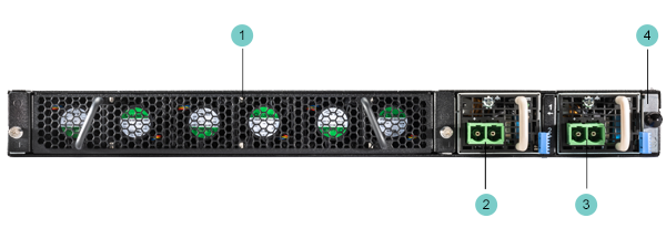
- Fan tray (removable)
- Power input panel 1 (DC terminal)
- Power input panel 2 (DC terminal)
- Chassis ground terminal
- Fan tray (removable)
- Power input panel 1 (HVDC power receptacle)
- Power input panel 2 (HVDC power receptacle)
- Chassis ground terminal
This platform includes all of the hardware components listed here.
| Quantity | Hardware |
|---|---|
| 1 | Power cables (black), AC power only, per platform configuration. Might include multiple power cable types if product is delivered outside of the US/Canada. By default, these platforms include one power supply unit (PSU) and one power cable: r5000 Series. |
| 2 | Power cables (black), AC power only, per platform configuration. Might include multiple power cable types if product is delivered outside of the US/Canada. By default, these platforms include two PSUs and two power cables: r10000/r12000 Series. |
| 4 | DC ring terminals, standard DC power only. By default, this platform includes two DC PSUs and four ring terminals. |
| 1 | RJ45 to DB9 console port cable (beige) |
| 1 | RJ45F to RJ45M rolled adapter (beige) |
| 1 | Quick-install rail kit |
| 2 | Rail lock brackets |
| 4 | M3 x 8mm flathead screws, black with patch |
For each platform, you might need to provide additional peripheral hardware. If you plan to remotely administer the system, it would be helpful to have a workstation already connected to the same subnet as the management interface.
|
Type of hardware |
Description |
|---|---|
|
Network hubs, switches, or connectors to connect to the platform network interfaces |
You must provide networking devices that are compatible with the network interface ports on the platform. You can use either 1/10/25/40/100-Gigabit Ethernet switches. |
|
USB flash drive |
You can use any USB-certified flash drive for installing upgrades and for system recovery. |
|
Serial console |
You can remotely manage the platform by connecting to a management console or console server through the console port. Important: In the event that network access is impaired or not yet configured, the serial console might be the only way to access the unit. You should perform all installations and upgrades using the serial console, as these procedures require reboots, in which network connectivity is lost temporarily. |
|
Management workstation on the same IP network as the platform |
You can use the default platform configuration if you have a management workstation set up. |
F5 rSeries platforms include a new software layer known as F5OS. F5OS is the operating system software for rSeries hardware, and it manages the configuration for software components, such as networking, tenants, and users.
For more information about installing and configuring F5OS on your F5 rSeries system, see these documents at Documentation - F5OS-A and F5 rSeries:
- F5 rSeries Systems: Getting Started
- F5 rSeries Systems: Software Installation and Upgrade
- F5 rSeries Systems: Administration and Configuration
The LCD touchscreen enables you to manage the platform without attaching a console or network cable. You can configure the display options to meet your needs.
To prolong the life of the backlight, the LCD will auto-dim the brightness when there has been no user activity for a period of 5 minutes. After an additional 10 seconds, the backlight will turn off entirely.
Touching anywhere on the LCD will restore the backlight to the operational brightness.
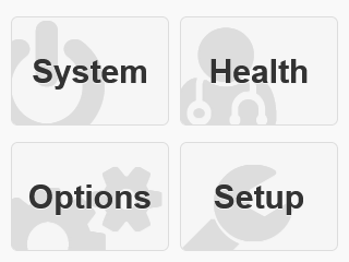
The LCD displays a splash screen by default. Tap the touchscreen to display the main menu, which displays options for navigating to the System, Health, Options, and Setup menus.
The LCD touchscreen also supports these modes:
Allows access to all options.
Allows access only to management and setup options. A padlock icon displays next to limited options.
Does not allow access to any options and displays only an image to indicate that the LCD touchscreen is disabled.
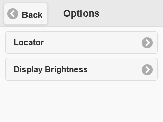
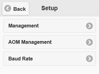
The main menu includes sections for accessing additional sub menus.
| Option | Description |
|---|---|
| System | Provides options for system control, including system reboot, reset, halt, power off, or power on. |
| Health | Provides LCD test option. |
| Options | Provides options for enabling/disabling the system locator LED and configuring LCD brightness. |
| Setup | Provides options for configuring the management interface, Always-On Management (AOM) management interface, and serial port baud rate. |
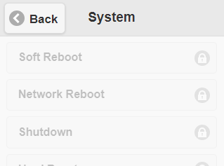
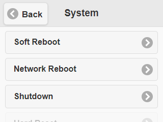
You can use the System menu to reboot, reset, halt, power off, or power on the system.
The available options vary depending on whether the LCD touchscreen is operating in secure or standard mode. For more information on configuring the modes, see LCD configuration overview. Approximate system boot time from power-on to login is 1 minute for both r5000 and r10000.
| Option | Description |
|---|---|
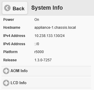
| System Info | Shows information about power state, hostname, IP addresses, platform, software version, AOM addresses and firmware, and LCD firmware version. This is disabled for security purposes when the LCD user interface is in Secure Mode, as indicated by a padlock icon. It is also disabled when the current state of Secure Mode is unknown. |
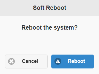
| Soft Reboot | Performs a properly-sequenced restart of the system. This is disabled for security purposes when the LCD user interface is in Secure Mode, as indicated by a padlock icon. It is also disabled when the current state of Secure Mode is unknown. Approximate system boot time from Soft Reboot to login is 2:45 minutes for r10000 and 1:45 minutes for r5000. |
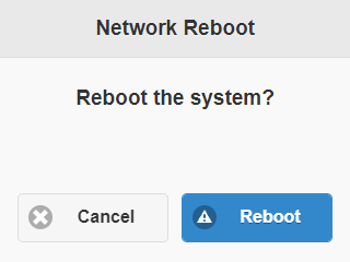
| Network Reboot | Performs a restart with network (PXE) booting. This is disabled for security purposes when the LCD user interface is in Secure Mode, as indicated by a padlock icon. It is also disabled when the current state of Secure Mode is unknown. Approximate system boot time from Network Reboot to login varies depending on network speed and boot image size. |
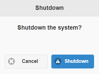
| Shutdown | Shuts down and powers off the system. This is disabled for security purposes when the LCD user interface is in Secure Mode, as indicated by a padlock icon. It is also disabled when the current state of Secure Mode is unknown. |
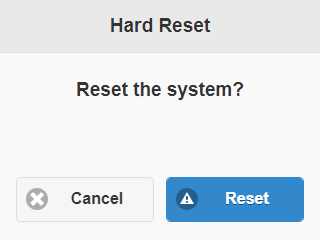
| Hard Reset | Performs a hard reset on the system. This is disabled for security purposes when the LCD user interface is in Secure Mode, as indicated by a padlock icon. It is also disabled when the current state of Secure Mode is unknown. Approximate system boot time from Hard Reset to login is 1 minute for both r10000 and r5000. |
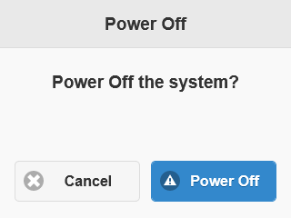
| Power Off | Powers off the system. Using this option to power off the system might result in data corruption. This is disabled for security purposes when the LCD user interface is in Secure Mode, as indicated by a padlock icon. It is also disabled when the current state of Secure Mode is unknown. |
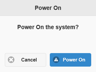
| Power On | Powers on the system. |
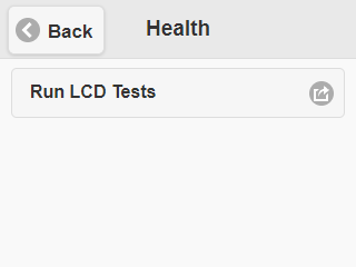
You can use the Health menu to view active alarms, view the event log, and run LCD tests.
| Option | Description |
|---|---|
| Active Alarms | The Active Alarms option is used to view alarms raised on the system. The total number of alarms is visible at the top of the Active Alarms page. Active alarms are organized by severity. Severities are Emergency, Alert, Critical, Error, Warning, Notice, and Info. The number of active alarms is indicated for each severity. Select the corresponding severity option to review all alarms for a given severity. |
| Event Log | The Event Log option is used to view the most recent event logs from the host. The Event Log is limited to 50 entries when viewed on the LCD. When there are more than 50 entries, the remaining events can be reviewed through the webUI or CLI. The Event Log page also provides a Clear All button to clear the event log. |
| Run LCD Tests | The Run LCD Tests option allows you to perform these tests: * Touchscreen - Verifies that the touchscreen functions correctly at nine locations in a 3x3 grid. * LCD Backlight - Verifies that the LCD backlight functions correctly. * Logo Ball - Verifies that the F5 logo ball functions correctly. * System LEDs - Verifies that the system status, system alarm, and power LEDs function correctly. |
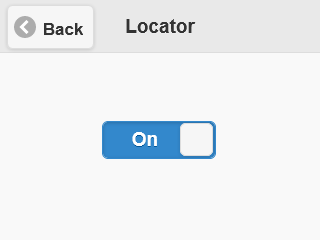
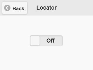
You can use the Options menu to enable/disable the system locator LED and configure LCD brightness.
| Option | Description |
|---|---|
| Locator LED | Controls the use of the system locator feature, which causes the F5 logo ball on the chassis front panel to flash on and off. Select from these options: * OFF (default) * ON |
| Display | Adjusts LCD backlight brightness from 10% to 100%. |
You can use the Setup menu to configure the management interface Always-On Management (AOM) management interface, and serial port baud rate.
Important: When using the LCD touchscreen to configure system or AOM management IP addresses, be sure to use the Commit option to save all settings.
| Option | Description |
|---|---|
| Management | Configures the front-panel management interface. Select from these options: * Enable IPv4 and/or IPv6 for the management address. * Enable or disable DHCP. The default value is disabled. * IPv4 Address - Sets an IPv4 management address. * IPv4 Prefix Length - Sets an IPv4 prefix length for the management address. * IPv4 Gateway - Sets an IPv4 gateway, or default route, for the management address. This route is necessary if you plan to manage the unit from a different subnetwork. * IPv6 Address - Sets an IPv6 management address. * IPv6 Prefix Length - Sets an IPv6 prefix length for the management address. * IPv6 Gateway - Sets an IPv6 gateway, or default route, for the management address. This route is necessary if you plan to manage the unit from a different subnetwork. |
| AOM Management | Configures the AOM management interface. Select from these options: * Enable IPv4 and/or IPv6 for the AOM management address. * Enable or disable DHCP. The default value is disabled. * IPv4 Address - Sets an IPv4 AOM management address. * IPv4 Prefix Length - Sets an IPv4 prefix length for the AOM management address. * IPv4 Gateway - Sets an IPv4 gateway, or default route, for the AOM management address. This route is necessary if you plan to manage the unit from a different subnetwork. * IPv6 Address - Sets an IPv6 AOM management address. * IPv6 Prefix Length - Sets an IPv6 prefix length for the AOM management address. * IPv6 Gateway - Sets an IPv6 gateway, or default route, for the AOM management address. This route is necessary if you plan to manage the unit from a different subnetwork. |
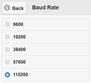
| Baud Rate | Changes the baud rate of the management serial port. Select from these options: * 9600 * 19200 (default) * 38400 * 57600 * 115200 |
To manage the platform using the LCD menu options, tap the touchscreen LCD to put it into menu mode. The LCD is operational even when the Host is powered off, provided that Always-On Management and the LCD are fully booted.
Important: It might take a few minutes for the LCD to become operational when the system is started from a powered off state.
When using the LCD to configure the unit, be sure to use the Commit option to save all settings.
You can use the touchscreen LCD to view a summary of system information.
Important: This is disabled for security purposes when the LCD user interface is in Secure Mode, as indicated by a padlock icon. It is also disabled when the current state of Secure Mode is unknown.
-
Touch the screen to activate the LCD menus.
-
Tap System
The System screen displays.
-
On the System screen, swipe up to scroll down and tap System Info.
-
Expand the AOM Info and LCD Info sections by tapping the plus sign (+)
-
Tap Back to return to the previous screen.
You can use the touchscreen LCD to perform a soft reboot of the system.
Important: This is disabled for security purposes when the LCD user interface is in Secure Mode, as indicated by a padlock icon. It is also disabled when the current state of Secure Mode is unknown.
-
Touch the screen to activate the LCD menus.
-
Tap System
The System screen displays.
-
On the System screen, swipe up to scroll down and tap Soft Reboot.
-
Tap Reboot. to confirm.
You can use the touchscreen LCD to perform a network reboot of the system.
Important: This is disabled for security purposes when the LCD user interface is in Secure Mode, as indicated by a padlock icon. It is also disabled when the current state of Secure Mode is unknown.
-
Touch the screen to activate the LCD menus.
-
Tap System
The System screen displays.
-
On the System screen, swipe up to scroll down and tap Network Reboot.
-
Tap Reboot. to confirm.
You can use the touchscreen LCD to shut down and power off the system.
Important: This is disabled for security purposes when the LCD user interface is in Secure Mode, as indicated by a padlock icon. It is also disabled when the current state of Secure Mode is unknown.
-
Touch the screen to activate the LCD menus.
-
Tap System
The System screen displays.
-
On the System screen, tap Shutdown.
-
Tap Shutdown. to confirm.
You can use the touchscreen LCD to halt the unit.
-
Touch the screen to activate the LCD menus.
-
Tap System
The System screen displays.
-
On the System screen, swipe up to scroll down and tap Hard Reset.
-
Tap Reset. to confirm.
You can use the touchscreen LCD to power the unit off and on.
-
Touch the screen to activate the LCD menus.
-
Tap System
The System screen displays.
-
On the System screen, swipe up to scroll down and tap Power Off or Power On.
-
Tap Power Off or Power On to confirm.
You can use the touchscreen LCD to verify LCD components, including the touchscreen, LCD backlight, F5 logo ball, and system LEDs.
-
Touch the screen to activate the LCD menus.
-
Tap Health.
The Health screen displays.
-
On the Health screen, tap Run LCD Tests.
The Touchscreen Test displays.
-
Tap Continue to begin the test.
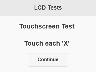
-
Tap each of the nine Xs that display, in sequence.
The test is complete after you have tapped all nine locations.

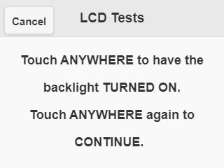
-
Next, you test the LCD backlight.
Tap anywhere on the screen to verify that the backlight functions correctly.
-
Next, you test the logo ball.
-
Tap Yes if the logo ball is flashing.

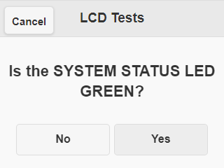
-
Finally, you test the system LEDs (status, alarm, power 1, and power 2).
You are prompted to verify each LED in sequence.
-
Tap Yes if each LED functions correctly.
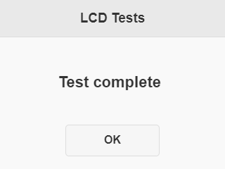
-
When all tests have completed, on the Test complete screen, press OK to return to the Health menu.
You can use the touchscreen LCD to enable the system locator. This flashes the F5 logo ball, enabling you to more easily locate the system in your data center.
-
Touch the screen to activate the LCD menus.
-
Tap Options. The Options screen displays.
-
On the Options screen, tap Locator.
When the locator is enabled, the logo ball will flash.
When the locator is disabled, the logo ball will no longer flash.
####ss Configure LCD brightness
You can use the touchscreen LCD to adjust the brightness of the display.
-
Touch the screen to activate the LCD menus.
-
Tap Options.
The Options screen displays.ww
-
On the Options screen, tap Display Brightness.
-
Tap plus (+) and minus (-) to adjust the brightness of the LCD in real-time.

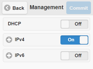
You can use the touchscreen LCD to configure whether to use DHCP to assign management addresses. When DHCP is enabled, manual configuration of management IP addresses is disabled.
-
Touch the screen to activate the LCD menus.
-
Tap Setup.
The Setup screen displays.
-
On the Setup screen, tap Management.
The Management screen displays.
-
For DHCP, tap to enable (On) or disable (Off) DHCP.
-
Tap Commit.
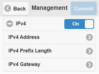
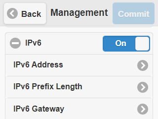
You can use the touchscreen LCD to configure management IP addresses manually if you are not enabling DHCP.
-
Touch the screen to activate the LCD menus.
-
Tap Setup.
The Setup screen displays.
-
On the Setup screen, tap Management.
The Management screen displays.
-
For DHCP, ensure that it is disabled (Off)
-
For IPv4 or IPv6, tap to enable (On).
-
[Expand the IPv4 or IPv6 section by tapping the plus sign (+) .]
-
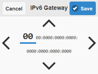
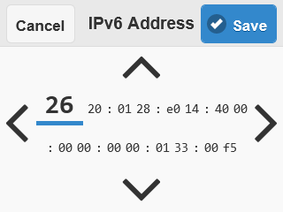
Tap IPv4 Address or IPv6 Address
-
Use the up and down arrows to increment/decrement values and the left and right arrows to select which octet to modify.


-
Click Save.
The Management screen displays.
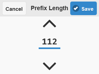
-
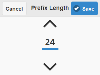
Tap Prefix Length.
-
Use the up and down arrows to increment/decrement values.
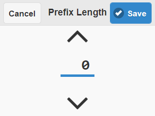
-
Click Save.
The Management screen displays.
-
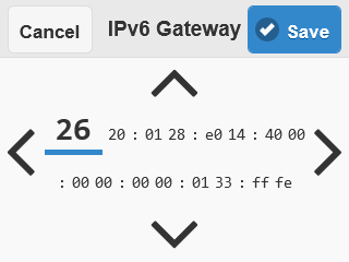
Tap IPv4 Gateway.
-
Use the up and down arrows to increment/decrement values and the left and right arrows to select which octet to modify.
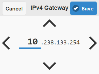
-
Click Save.
-
Tap Commit.
You can use the touchscreen LCD to configure whether to use DHCP to assign the Always-On Management (AOM) management address. For more information about AOM, see Always-On Management overview
When DHCP is enabled, manual configuration of the AOM management IP address is disabled.
-
Touch the screen to activate the LCD menus.
-
Tap Setup.
The Setup screen displays.
-
On the Setup screen, tap AOM Management.
The AOM Mgmt screen displays.
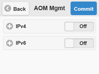
-
Expand the IPv4 or IPv6 section by tapping the plus sign (+).
-
For DHCP, tap to enable (On).
-
Tap Commit.
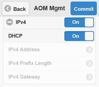
You can use the touchscreen LCD to configure management IP addresses manually if you are not enabling DHCP.
-
Touch the screen to activate the LCD menus.
-
Tap Setup.
The Setup screen displays.
-
On the Setup screen, tap AOM Management.
The AOM Mgmt screen displays.
-
For IPv4 or IPv6, tap to enable (On).
-
Expand the IPv4 or IPv6 section by tapping the plus sign (+).
-
For DHCP, ensure that it is disabled (Off).
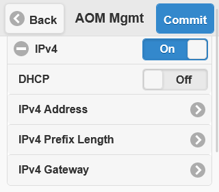
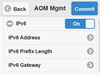
-
Tap IPv4 Address or IPv6 Address
-
Use the up and down arrows to increment/decrement values and the left and right arrows to select which octet to modify.
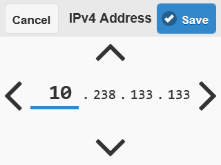
-
Click Save.
The AOM Mgmt screen displays.
-
Tap Prefix Length.
-
Use the up and down arrows to increment/decrement values.
-
Click Save.
The AOM Mgmt screen displays.
-
Tap IPv4 Gateway.
-
Use the up and down arrows to increment/decrement values and the left and right arrows to select which octet to modify.

-
Click Save.
-
Tap Commit.
You can use the touchscreen LCD to configure the baud speed for connecting to the front-panel serial port from a serial console.
-
Touch the screen to activate the LCD menus.
-
Tap Setup.
The Setup screen displays.
-
On the Setup screen, tap Baud Rate.
-
Select which baud rate to use for the front-panel serial port.
-
Tap Back to return to the previous screen.
You can configure options, including operational mode, for the LCD touchscreen from the CLI.
You can show the current mode for the LCD touchscreen from the CLI.
-
Log in to the command line interface (CLI) of the system using an account with admin access. When you log in to the system, you are in user (operational) mode.
-
Show which LCD mode is currently configured.
show components component lcdA summary similar to this example displays:
appliance-1# show components component lcd
components component lcd
state serial-no sub0872g00ct
state part-no "SUB-0872-02 REV 1"
state empty false
state mode standard
The LCD touchscreen supports a secure mode, which allows access only to management and setup options. No customer data is shown. You can enable secure mode for the LCD touchscreen from the CLI.
-
Log in to the command line interface (CLI) of the system using an account with admin access.
When you log in to the system, you are in user (operational) mode.
-
Change to config mode.
configThe CLI prompt changes to include
(config). -
Enable secure mode for the LCD.
components component lcd config mode secureIn this example, you enable secure mode for the LCD:
appliance-1(config)# components component lcd config mode secure -
Commit the configuration changes.
commit
You can choose to disable the LCD touchscreen from the CLI. This prevents access to all options and shows only an image to indicate that it is disabled.
-
Log in to the command line interface (CLI) of the system using an account with admin access.
When you log in to the system, you are in user (operational) mode.
-
Change to config mode.
configThe CLI prompt changes to include
(config). -
Enable standard mode for the LCD.
components component lcd config mode disabledIn this example, you disable the LCD:
appliance-1(config)# components component lcd config mode disabled -
Commit the configuration changes.
commit
You can choose to enable standard mode for the LCD touchscreen from the CLI. This allows access to all options.
-
Log in to the command line interface (CLI) of the system using an account with admin access.
When you log in to the system, you are in user (operational) mode.
-
Change to config mode.
configThe CLI prompt changes to include
(config). -
Enable standard mode for the LCD.
components component lcd config mode standardIn this example, you enable standard mode for the LCD:
appliance-1(config)# components component lcd config mode standard -
Commit the configuration changes.
commit
The behavior of the various LEDs on the platform indicate the status of the system or component.
The status LED indicates the operating state of the system.
| State | Description |
|---|---|
| off/none | System is powered down, or LCD module has failed. |
| green solid | System is running in normal mode. |
| amber solid | System is running in an impaired mode or is operating in one of these conditions: * It is in the standby power state * It is powered on and in the process of booting * It is powered on, but offline |
| amber/yellow blinking | System might be in a state in which a software or hardware problem is interfering with control of the LCD or communication is lost between the system and the LCD. |
The alarm LED indicates system alarm conditions and the severity of the alarm condition.
There are five levels of messages.
Note: The alarm LED shows the highest severity of active alarms. Clearing the event log does not turn off the LED. The LED turns off when the alarm condition is fixed.
| State | Description |
|---|---|
| off/none | Informational or no alarm conditions are present. System is operating properly, is completely unpowered, or the LCD module has failed. |
| amber/yellow solid | Warning (4). System might not be operating properly, but the condition is not severe or potentially damaging. An error will occur if action is not taken. |
| amber/yellow blinking | Error (3). System is not operating properly, but the condition is not severe or potentially damaging. Notifications about error conditions, but the system is not unusable. |
| red solid | Alert (1) or Critical (2). System is not operating properly, and the condition is potentially damaging. Requires immediate attention. |
| red blinking | Emergency (0). System is not operating, and the condition is potentially damaging. System is not usable. |
The management port LED indicates the link and activity status of the management port.
| LED | State | Description |
|---|---|---|
| link | off/none | Not linked. |
| green solid | Linked at 1GbE. | |
| amber solid | Linked at 10MbE or 100MbE. | |
| activity | off/none | Not linked or link is idle. |
| green blinking | Link is actively transmitting or receiving data. |
The F5 logo ball on the front of the chassis indicates when the platform has valid input power and can also function as a system locator.
You can enable the system locator from the touchscreen LCD.
For more information, see lcd-enable-system-locator.dita
| State | Description |
|---|---|
| on | System has valid input power applied. |
| blinking | System locator function is enabled (only available when the platform is powered on). |
| off | System is powered completely off. |
The Power 1 and Power 2 LEDs on the front of the chassis indicate the general operating state of the power supply units (PSUs).
| Power supply state | Description |
|---|---|
| green solid | PSU is present and operating properly. Also indicates when the system is in power standby mode. |
| amber/yellow solid | PSU is present and operating in one of these conditions: * PSU not powered * PSU has experienced a fault or failure * Mismatched PSU configuration detected * Unidentified PSU configuration detected |
| off/none | PSU is not present or not fully seated in the chassis. |
The LEDs located on the 650W AC power supply units (PSUs) indicate PSU operating state.
| Input LED | Output LED | Condition (PWR-0306-xx) |
|---|---|---|
| green solid | green solid | Normal operation |
| off | off | Fault: Input UV, Input OV, VSB SC |
| off | amber/yellow solid | Not valid |
| green solid | amber/yellow solid | Warning: VSB OC Fault: Fan, OTP, OC, VOUT OV/UV |
| green solid | amber/yellow blinking | Warning: FAN, OTP, OC, VOUT OV/UV |
| green blinking | amber/yellow solid | Fault: Input OV |
| green blinking | amber/yellow blinking | Warning: Input OV, Input UV |
| green blinking | off | Not valid |
| green solid | green blinking | PS_ON_L is high |
| green solid | off | PS_KILL PSU not inserted |
OV - Over Voltage; OTP - Over Temperature Protection; UV - Under Voltage; OC - Over Current; VSB - Standby Voltage
The LEDs located on the DC power supply units (PSUs) indicate PSU operating state.
| Input LED | Output/Fault LED | Condition (PWR-0307-xx) |
|---|---|---|
| green solid | green solid | Normal operation |
| off | off | Fault: Input UV, VSB SC |
| off | amber/yellow solid | Not valid |
| green solid | amber/yellow solid | Warning: VSB OC Fault: Fan, OTP, OC, VOUT OV/UV |
| green solid | amber/yellow blinking | Warning: FAN, OTP, OC, VOUT OV/UV |
| green blinking | amber/yellow solid | Fault: Input OV |
| green blinking | amber/yellow blinking | Warning: Input OV, Input UV |
| green blinking | off | Not valid |
| green solid | green blinking | PS_ON_L is high |
| green solid | off | PS_KILL PSU not inserted |
OV - Over Voltage; OTP - Over Temperature Protection; UV - Under Voltage; OC - Over Current; VSB - Standby Voltage
The LEDs located on the DC power supply units (PSUs) indicate PSU operating state.
| Input LED | Output/Fault LED | Condition (PWR-0378-xx) |
|---|---|---|
| green solid | green solid | Normal operation |
| off | off | Fault: Input UV |
| off | amber/yellow solid | Not valid |
| green solid | amber/yellow solid | Warning: VSB OC Fault: Fan, OTP, OC, VOUT OV/UV |
| green solid | amber/yellow blinking | Warning: FAN, OTP, OC, VOUT OV/UV |
| green blinking | amber/yellow solid | Fault: Input OV |
| green blinking | amber/yellow blinking | Warning: Input OV, Input UV |
| green blinking | off | Not valid |
| green solid | green blinking | PS_ON is high |
| green solid | off | PS_KILL PSU not inserted |
OV - Over Voltage; OTP - Over Temperature Protection; UV - Under Voltage; OC - Over Current; VSB - Standby Voltage
The LEDs located on the 1200W AC power supply units (PSUs) indicate PSU operating state.
| Input LED | Output LED | Condition (PWR-0388-xx) |
|---|---|---|
| green solid | green solid | Normal operation |
| off | off | Fault: Input UV, Input OV, VSB SC |
| off | amber/yellow solid | Not valid |
| green solid | amber/yellow solid | Warning: VSB OC Fault: Fan, OTP, OC, VOUT OV/UV |
| green solid | amber/yellow blinking | Warning: FAN, OTP, OC, VOUT OV/UV |
| green blinking | amber/yellow solid | Fault: Input OV |
| green blinking | amber/yellow blinking | Warning: Input OV, Input UV |
| green blinking | off | Not valid |
| green solid | green blinking | PS_ON_L is high |
| green solid | off | PS_KILL PSU not inserted |
OV - Over Voltage; OTP - Over Temperature Protection; UV - Under Voltage; OC - Over Current; VSB - Standby Voltage
The LEDs located on the 1200W DC power supply units (PSUs) indicate PSU operating state.
| Input LED | Output/Fault LED | Condition (PWR-0385-xx) |
|---|---|---|
| green solid | green solid | Normal operation |
| off | off | Fault: Input UV |
| off | amber/yellow solid | Not valid |
| green solid | amber/yellow solid | Warning: VSB OC Fault: Fan, OTP, OC, VOUT OV/UV |
| green solid | amber/yellow blinking | Warning: FAN, OTP, OC, VOUT OV/UV |
| green blinking | amber/yellow solid | Fault: Input OV |
| green blinking | amber/yellow blinking | Warning: Input OV, Input UV |
| green blinking | off | Not valid |
| green solid | green blinking | PS_ON is high |
| green solid | off | PS_KILL PSU not inserted |
OV - Over Voltage; OTP - Over Temperature Protection; UV - Under Voltage; OC - Over Current; VSB - Standby Voltage
Every platform includes multiple interfaces. The exact number of interfaces that are on the system depends on the platform type.
Each interface on the platform has a set of properties that you can configure, such as enabling or disabling the interface, setting the requested media type and duplex mode, and configuring Ethernet flow control.
The r2000/r4000 Series platforms include 25G (SFP28) ports (5.0-8.0), in which you can use 25G (SFP28), 10G (SFP+) or 1G (SFP) transceiver modules.
On platforms that include 100G interface ports, you can use only F5-branded 100G QSFP28 transceiver modules in those ports.
When a 100G interface operates at either 40G and 100G speeds, it is considered to be bundled. On the r10000/r12000S platform, the 100G ports (1, 2, 11, and 12) default to 100G. The cable that you use when operating at 100G with 100GBASE-SR4 transceiver modules is an industry-standard OM4 qualified multi-mode fiber optic cable with female MPO/MTP connectors at both ends. The cable that you use with 100GBASE-LR4 transceiver modules is an industry-standard SMF fiber optic cable with LC duplex connectors and a reach of up to 10km. You must provide your own cable and F5-branded QSFP28 transceiver modules for 100G operation.
The fiber SFP interfaces are set to default and native speeds for 10GB and 25GB. The 1GB interface is set to auto negotiate. For copper SFP, both 1GB and 10GB are set to auto negotiate. We recommend that you also configure any network equipment that you plan to use with the system to auto-negotiate speed and duplex settings. If you connect the system to network devices with forced speed and duplex settings, you must force the speed and duplex settings of the system to match the settings of the other network device.
Important: If the system is attempting to auto-negotiate interface settings with an interface that has the speed and duplex settings forced (that is, auto-negotiation is disabled), you will experience severe performance degradation.
The system provides restrictions to prevent you from configuring an interface with invalid settings.
Important: Auto-MDI/MDIX functionality is retained when you manually configure an interface to use specific speed and duplex settings. You can use either a straight-through cable or a crossover cable when media settings are forced, and you will be able to successfully link to either DTE or DCE devices.
You can configure the front-panel management port on this platform from the CLI or webUI.
You can enable the management port from the CLI.
-
Connect to the system using a management console or console server.
The default baud rate and serial port configuration is 19200/8-N-1.
-
Log in to the command line interface (CLI) of the system with admin access.
When you log in to the system, you are in user (operational) mode.
-
Change to config mode.
configThe CLI prompt changes to include (config).
-
[Enable the specified management port.] [interfaces interface mgmt config enable] In this example, you enable the management port on the platform:
appliance-1(config)# interfaces interface mgmt config enable-
Return to user (operational) mode.
end -
Verify that the management interface is enabled.
show interfaces interface mgmt state enabledA summary similar to this example displays:
appliance-1# show interfaces interface mgmt state enabled
state enabled true
You can disable the management port from the CLI.
-
Log in to the command line interface (CLI) of the system with admin access.
When you log in to the system, you are in user (operational) mode.
-
Change to config mode.
configThe CLI prompt changes to include (config).
-
Disable the specified management port.
interfaces interface mgmt config disabledIn this example, you enable the management port on the platform:
appliance-1(config)# interfaces interface mgmt config disabled -
Return to user (operational) mode.
end -
Verify that the management interface is disabled.
show interfaces interface mgmt state enabledA summary similar to this example displays:
appliance-1# show interfaces interface mgmt state enabled
state enabled false
You can configure auto-negotiation for the management port from the CLI.
-
Log in to the command line interface (CLI) of the system with admin access.
When you log in to the system, you are in user (operational) mode.
-
Change to config mode.
configThe CLI prompt changes to include (config).
-
Configure auto-negotiation for the management port.
interfaces interface mgmt ethernet config auto-negotiate { [true] \| [false] }In this example, you enable auto-negotiation:
appliance-1(config)# interfaces interface mgmt ethernet config auto-negotiate true -
Commit the configuration changes.
commit
You can configure duplex mode for the management port from the CLI.
-
Log in to the command line interface (CLI) of the system with admin access.
When you log in to the system, you are in user (operational) mode.
-
Change to config mode.
configThe CLI prompt changes to include (config).
-
Configure duplex mode for the management port.
interfaces interface mgmt ethernet config duplex-mode { [FULL] \| [HALF] }In this example, you configure the management port to be full speed:
appliance-1(config)# interfaces interface mgmt ethernet config duplex-mode FULL -
Commit the configuration changes.
commit
You can configure port speed for the management port from the CLI.
-
Log in to the command line interface (CLI) of the system with admin access.
When you log in to the system, you are in user (operational) mode.
-
Change to config mode.
configThe CLI prompt changes to include (config).
-
Configure the port speed for the management port.
interfaces interface mgmt ethernet config port-speed {[SPEED_1GB] \| [SPEED_10MB] \| [SPEED_100MB] }In this example, you configure the management port to use 100MB speed:
appliance-1(config)# interfaces interface mgmt ethernet config port-speed SPEED_100MB -
Commit the configuration changes.
commit
You can manage the front-panel interfaces on the platform from the CLI or webUI.
You can show the status of all interfaces on the platform from the webUI.
-
Log in to the webUI using an account with admin access.
-
On the left, click [NETWORK SETTINGS > Interfaces
A table showing all interfaces displays.
You can configure front-panel interfaces from the CLI.
-
Log in to the command line interface (CLI) of the system with admin access.
When you log in to the system, you are in user (operational) mode.
-
Change to config mode.
configThe CLI prompt changes to include (config).
-
Configure settings for the specified interface.
interfaces interface \<interface> config { disabled \|enabled } description <interface-description> type <interface-type>]In this example, you enable and configure interface 1.0 with a custom description:
appliance-1(config)# interfaces interface 1.0 config enabled description
"Interface 1.0"
Note: Changing the MTU at the platform level would affect all tenants, so this is configurable at the tenant level for greater control.
-
Commit the configuration changes.
commit
You can show the state of a specific interface on a platform from the CLI.
-
Log in to the command line interface (CLI) of the system with admin access.
When you log in to the system, you are in user (operational) mode.
-
Display the current status of a specific interface.
show interface interface <interface-number>appliance-1# show interfaces interface 1.0 interfaces interface 1.0 state name 1.0 state type ethernetCsmacd state mtu 9600 state enabled true state ifindex 19 state oper-status DOWN state counters in-octets 0 state counters in-unicast-pkts 0 state counters in-broadcast-pkts 0 state counters in-multicast-pkts 0 state counters in-discards 0 state counters in-errors 0 state counters in-fcs-errors 0 state counters out-octets 0 state counters out-unicast-pkts 0 state counters out-broadcast-pkts 0 state counters out-multicast-pkts 0 state counters out-discards 0 state counters out-errors 0 state forward-error-correction auto state lacp_state LACP_DEFAULTED ethernet state port-speed SPEED_100GB ethernet state hw-mac-address 00:98:a1:76:54:0d ethernet state counters in-mac-control-frames 0 ethernet state counters in-mac-pause-frames 0 ethernet state counters in-oversize-frames 0 ethernet state counters in-jabber-frames 0 ethernet state counters in-fragment-frames 0 ethernet state counters in-8021q-frames 0 ethernet state counters in-crc-errors 0 ethernet state counters out-mac-control-frames 0 ethernet state counters out-mac-pause-frames 0 ethernet state counters out-8021q-frames 0 ethernet state flow-control rx on
You can show the state of all interfaces on the platform from the CLI.
-
Log in to the command line interface (CLI) of the system with admin access.
When you log in to the system, you are in user (operational) mode.
-
Show the current state of all interfaces.
show interfaces interfaceA summary similar to this example displays:
appliance-1# show interfaces interface state oper-status
OPER
NAME STATUS
--------------
1.0 UP
2.0 UP
3.0 DOWN
4.0 DOWN
5.0 DOWN
6.0 DOWN
7.0 DOWN
8.0 DOWN
9.0 DOWN
10.0 DOWN
11.0 DOWN
12.0 DOWN
13.0 DOWN
14.0 DOWN
15.0 DOWN
16.0 DOWN
17.0 DOWN
18.0 DOWN
19.0 DOWN
20.0 DOWN
mgmt UP
You can show statistics for all interfaces from the CLI.
-
Log in to the command line interface (CLI) of the system with admin access.
When you log in to the system, you are in user (operational) mode.
-
Show statistics for all interfaces.
show interfaces interface state countersPossible completions include:
in-broadcast-pkts
in-discards
in-errors
in-fcs-errors
in-multicast-pkts
in-octets
in-unicast-pkts
out-broadcast-pkts
out-discards
out-errors
out-multicast-pkts
out-octets
out-unicast-pkts
A summary similar to this example displays:
appliance-1# show interfaces interface state counters
interfaces interface 1.0
state counters in-octets 0
state counters in-unicast-pkts 0
state counters in-broadcast-pkts 0
state counters in-multicast-pkts 0
state counters in-discards 0
state counters in-errors 0
state counters in-fcs-errors 0
state counters out-octets 0
state counters out-unicast-pkts 0
state counters out-broadcast-pkts 0
state counters out-multicast-pkts 0
state counters out-discards 0
state counters out-errors 0
interfaces interface 2.0
state counters in-octets 0
state counters in-unicast-pkts 0
state counters in-broadcast-pkts 0
state counters in-multicast-pkts 0
state counters in-discards 0
state counters in-errors 0
state counters in-fcs-errors 0
state counters out-octets 0
state counters out-unicast-pkts 0
state counters out-broadcast-pkts 0
state counters out-multicast-pkts 0
state counters out-discards 0
state counters out-errors 0
...
You can show the current running configuration for all interfaces from the CLI.
-
Log in to the command line interface (CLI) of the system with admin access.
When you log in to the system, you are in user (operational) mode.
-
Show the current running configuration for all interfaces.
show running-config interfaces interfaceA summary similar to this example displays:
appliance-1# show running-config interfaces interface
interfaces interface 1.0
config name 1.0
config type ethernetCsmacd
config enabled
!
interfaces interface 2.0
config name 2.0
config type ethernetCsmacd
config enabled
!
interfaces interface 3.0
config name 3.0
config type ethernetCsmacd
config enabled
!
...
You can show the current running configuration of VLAN interface members from the CLI.
-
Log in to the command line interface (CLI) of the system with admin access.
When you log in to the system, you are in user (operational) mode.
-
Show the current running configuration of VLAN interface members.
show running-config interfaces interface ethernet switched-vlanA summary similar to this example displays:
appliance-1# show running-config interfaces interface ethernet switched-vlan
interfaces interface 1.0
ethernet switched-vlan config trunk-vlans [ 2001 ]
!
You can reset counters for specified interfaces from the CLI.
-
[Log in to the command line interface (CLI) of the system using an account with admin access.]When you log in to the system, you are in user (operational) mode.
-
[Change to config mode.][config]The CLI prompt changes to include [(config)].
-
[Reset counters for specified interfaces.] [reset counters interfaces [ <
interface-number> ]] In this example, you reset counters for interfaces 1.0 and 2.0:
appliance-1(config)# reset counters interfaces [1.0 2.0]- [Commit the configuration changes.][commit] .userinput
You can create a LAG interface from the CLI.
-
Log in to the command line interface (CLI) of the system with admin access.
When you log in to the system, you are in user (operational) mode.
-
Change to config mode.
configThe CLI prompt changes to include (config).
-
Create a LAG interface.
interfaces interface <lag-name> configPossible completions include:
aggregation
config
hold-time
In this example, you create an IEEE 802ad LAG interface named “new-lag”:
appliance-1(config)# interfaces interface new-lag config type ieee802adLag -
Commit the configuration changes.
commit
You can show the current running configuration for LAG interfaces from the CLI.
-
Log in to the command line interface (CLI) of the system with admin access.
When you log in to the system, you are in user (operational) mode.
-
Show the current running configuration for LAG interfaces.
show running-config interfaces interface <lag-name> aggregationWhen you specify a LAG interface, a summary similar to this example displays:
appliance-1# show running-config interfaces interface lag-test aggregation
interfaces interface lag-test
aggregation config lag-type STATIC
aggregation config distribution-hash src-dst-ipport
You can associate an interface with a specified LAG from the CLI.
-
Log in to the command line interface (CLI) of the system with admin access.
When you log in to the system, you are in user (operational) mode.
-
Change to config mode.
configThe CLI prompt changes to include (config).
-
Associate an interface with a specified LAG.
interfaces interface <interface-number> ethernet config aggregate-id <lag-name>In this example, you associate interface 1.0 with a LAG named “new-lag”:
appliance-1(config)# interfaces interface 1.0 ethernet config aggregate-id new-lag -
Commit the configuration changes.
commit
The front-panel QSFP28 100G ports on r5000/r10000/r12000S Series systems support port group functionality. Port groups enable you to change which mode, or port speed, that port uses. QSFP28 ports operate at 100G by default, but depending on the optical transceiver module that you have installed in the port, you can configure the port group to use one of these modes:
100G mode Creates one interface at 100G speed. This is the default mode for 100G ports.
40G mode Creates one interface at 40G speed. This is the default mode for 40G ports.
Changing the mode for a port group reboots the system, removes stale interfaces from your configuration, and removes any references to stale interfaces from your configuration. You will then need to reconfigure any previously-configured protocols to use the modified port group.
The system creates and breaks down interfaces based on how you have configured port groups.
| Optical Transceiver Module | Port Group Mode | Interfaces |
|---|---|---|
| QSFP28 | 100G | x.0 |
| QSFP+ | 40G | x.0 |
You can configure a port group for the interfaces on the system at either 100G or 40G speeds from the CLI. .
-
Log in to the command line interface (CLI) of the system with admin access.
When you log in to the system, you are in user (operational) mode.
-
Change to config mode.
configThe CLI prompt changes to include (config).
-
Configure port groups for a specific interface.
portgroups portgroup <interface-number> config mode { MODE_100GB | MODE_40GB }In this example, you configure the port group mode on interface 2 to use the 100GB mode:
appliance-1(config)# portgroups portgroup 2 config mode MODE_100GB -
Commit the configuration changes.
commit
You can show the state for port groups on the system from the CLI.
-
Log in to the command line interface (CLI) of the system with admin access.
When you log in to the system, you are in user (operational) mode.
-
Show the current state for the port groups configuration.
show portgroups portgroup
A summary similar to this example displays:
```
appliance-1# show portgroups portgroup
portgroups portgroup 1
state vendor-name "F5 INC."
state vendor-oui 009065
state vendor-partnum "OPT-0031 "
state vendor-revision A0
state vendor-serialnum "A1B2C3D40 "
state transmitter-technology "850 nm VCSEL"
state media 100GBASE-SR4
state optic-state QUALIFIED
state ddm rx-pwr low-threshold alarm -14.0
state ddm rx-pwr low-threshold warn -11.0
state ddm rx-pwr instant val-lane1 -1.96
state ddm rx-pwr instant val-lane2 -0.95
state ddm rx-pwr instant val-lane3 -1.06
state ddm rx-pwr instant val-lane4 -1.98
state ddm rx-pwr high-threshold alarm 3.4
state ddm rx-pwr high-threshold warn 2.4
state ddm tx-pwr low-threshold alarm -10.0
state ddm tx-pwr low-threshold warn -8.0
state ddm tx-pwr instant val-lane1 0.07
state ddm tx-pwr instant val-lane2 0.67
state ddm tx-pwr instant val-lane3 0.32
state ddm tx-pwr instant val-lane4 0.45
state ddm tx-pwr high-threshold alarm 5.0
state ddm tx-pwr high-threshold warn 3.0
state ddm temp low-threshold alarm -5.0
state ddm temp low-threshold warn 0.0
state ddm temp instant val 40.8046
state ddm temp high-threshold alarm 75.0
state ddm temp high-threshold warn 70.0
state ddm bias low-threshold alarm 0.003
state ddm bias low-threshold warn 0.005
state ddm bias instant val-lane1 0.00753
state ddm bias instant val-lane2 0.007448
state ddm bias instant val-lane3 0.007536
state ddm bias instant val-lane4 0.007504
state ddm bias high-threshold alarm 0.013
state ddm bias high-threshold warn 0.011
state ddm vcc low-threshold alarm 2.97
state ddm vcc low-threshold warn 3.135
state ddm vcc instant val 3.3027
state ddm vcc high-threshold alarm 3.63
state ddm vcc high-threshold warn 3.465
...
```
The appearance and behavior of the network interface LEDs on the platform indicate network traffic activity, interface speed, and interface duplexity.
The appearance and behavior of the SFP28 port LEDs indicate network traffic activity, interface speed, and interface duplexity.
| State | Module | Description |
|---|---|---|
| off (not lit) | SFP28 or SFP+ | No link. |
| amber/yellow solid | SFP28 or SFP+ | Linked at 25GbE/10GbE. |
| amber/yellow blinking | SFP28 or SFP+ | Link is actively transmitting or receiving data at 25GbE/10GbE. |
The appearance and behavior of the QSFP28/ QSFP+ port LEDs indicate network traffic activity, interface speed, and interface duplexity.
| State | Module | Description |
|---|---|---|
| off (not lit) | QSFP+ or QSFP28 | No link. |
| blue solid | QSFP28 | Linked at 100GbE (with all four LEDs operating in unison). |
| blue blinking | QSFP28 | Link is actively transmitting or receiving data at 100GbE (with all four LEDs operating in unison). |
| green solid | QSFP+ | Linked at 40GbE when operating as a single 40GbE port (with all four LEDs operating in unison). |
| green blinking | QSFP+ | Link is actively transmitting or receiving data at 40GbE (with all four LEDs operating in unison). |
| amber/yellow solid | QSFP28 | Linked at 25GbE when operating as a single 4x 25GbE ports. |
| amber/yellow solid | QSFP+ | Linked at 10GbE when operating as a single 4x 10GbE ports. |
| amber/yellow blinking | QSFP28 | Link is actively transmitting or receiving data at 25GbE. |
| amber/yellow blinking | QSFP+ | Link is actively transmitting or receiving data at 10GbE. |
The Always-On Management (AOM) subsystem enables you to manage the system remotely from a serial console, even if the host is powered down. The AOM Command Menu operates independently of F5OS.
You can use the command menu to reset the unit if the system has locked up or get access to the system directly, so that you can configure it from the command-line interface.
You can access the AOM Command Menu after connecting to the front panel serial console.
-
Connect to the system using a management console or console server.
The default baud rate and serial port configuration is 19200/8-N-1.
-
Open the AOM Command Menu.
Esc (
Quitting the AOM Command Menu returns you to the system console.
The AOM Command Menu provides the AOM options for the platform. You can access the AOM Command Menu from a serial console.
The availability of menu options varies depending on the platform type.
| Letter | Option | Description |
|---|---|---|
| A | Reset AOM | Resets the AOM subsystem. |
| B | Set baud rate | Configures the baud speed for connecting to AOM from the serial console. These options are available: * 9600 * 19200 (default) * 38400 * 57600 * 115200 |
| I | Display platform information | Displays information about the AOM firmware and bootloader; chassis serial number, power status for the active console, front-panel USB port status, and system runtime status; power supply unit (PSU) status and serial numbers; and FIPS initialization error status (if applicable). |
| N | Configure AOM network | Runs the AOM network configuration utility. This utility enables you to reconfigure the IP address, netmask, and default gateway used by AOM. If you use this option while connected using SSH, your session will be disconnected as a part of the network configuration operation. This option is not available when you are connected using SSH. |
| P | Power on/off host subsystem | Powers the host subsystem on or off. F5 does not recommend using this option under normal circumstances. It does not allow for graceful shutdown of the system. |
| R | Reset host subsystem | Resets the host subsystem with a hardware reset. F5 does not recommend using this option under normal circumstances. It does not allow for graceful shutdown of the system. |
| S | Configure SSH Server | Sets a session idle timeout (in seconds) for the AOM SSH server. Available values are 0 (no timeout; default value), or between 30 and 86400 (one day). |
| U | Front panel USB port | Enables or disables the front-panel USB port on the platform. When you change the USB port configuration, the system must restart for the change to take effect. The BIOS enables/disables the USB port as configured during startup. |
| Q | Quit menu and return to console | Exits the AOM Command Menu and returns to terminal emulation mode. |
If you would like to access AOM over the network rather than using the serial console, you need to create an AOM user. This account is created on the AOM subsystem only and is not saved to your F5OS system configuration.
-
Connect using SSH to the management IP address.
-
Log in to the command line interface (CLI) of the system with admin access.
When you log in to the system, you are in user (operational) mode.
-
Change to config mode.
configThe CLI prompt changes to include (config).
-
Type
system aom set-ssh-user-info. -
Type the user name you want.
-
Type the required password.
When the account creation is successful, a message similar to this one displays: AOM SSH username and password set successfully.
You can assign a management IP address, netmask, and gateway to access AOM either manually or with DHCP.
-
Connect to the system using a management console or console server.
The default baud rate and serial port configuration is 19200/8-N-1.
-
Open the AOM Command Menu.
Esc ( -
Type
nto open the AOM management network configurator. -
Assign a management IP address, netmask, and gateway:
 - To use DHCP to assign the addresses, enter `y` when prompted about using DHCP.
 - To manually assign the addresses, enter `n` when prompted about using DHCP. At the prompts, type values for IP address (required), netmask (required), and gateway (optional).
A confirmation message displays the configured management IP address, netmask, and gateway.
-
Type
ito verify the assigned addresses.
Before you access the AOM Command Menu using SSH, you must assign a management IP address, netmask, and gateway for AOM. You can assign the addresses manually or with DHCP. You must also create an AOM admin user account.
You can access the AOM Command Menu remotely using SSH from a management workstation connected to the same subnet as the platform’s management (MGMT) interface.
On this platform, AOM allows only one SSH connection at a time.
-
Open an SSH session, where
<aom-username>is the AOM admin user account that you configured for the system, and<ip-address>is the IP address that you configured for AOM.ssh <aom-username>@<ip-address> -
Type the previously configured AOM user password.
-
Open the AOM Command Menu.
Esc (
You can specify a timeout value (in seconds) for idle AOM SSH sessions. You can access the AOM Command Menu using either a serial console or SSH.
-
Connect to the system using a management console or console server.
The default baud rate and serial port configuration is 19200/8-N-1.
-
Open the AOM Command Menu.
Esc ( -
Type
sto configure a timeout value for idle SSH sessions. -
Type a timeout value.
The default value is 0 (no timeout). Available values are 0, or between 30 and 86400 (one day).
You can connect to the system's serial console to disable SSH access to AOM over the network. This does not affect console access to AOM.
-
Connect to the system using a management console or console server.
The default baud rate and serial port configuration is 19200/8-N-1.
-
Open the AOM Command Menu.
Esc ( -
Type
nto open the AOM management network configurator. -
When prompted about using DHCP, enter
n. -
At the IP address prompt type
0.0.0.0A confirmation message displays the configured management IPaddress, netmask, and gateway.
-
Type
ito verify that network configuration is disabled.