Updated Date: 07/07/2026
Repackaging Guidelines
If it becomes necessary to transport the chassis to another location or return it to F5, these guidelines will help ensure that you repackage the chassis properly.
You can perform a disk erase operation to erase all sensitive data from storage drives before you return a chassis to F5. For more information, see F5 Platforms: Essentials at techdocs.f5.com/en-us/hw-platforms/f5-plat-hw-essentials.html.
Important: Before returning any equipment, contact F5 to obtain a Service Order (SO) or Return Material Authorization (RMA) case number.
Important: You must use shipping materials and packaging provided by F5 when repackaging the chassis.
Note: Be sure to keep a record of the tracking number and ship date. These will be needed to track lost shipments.
Note: Do not include any cables, removable optical transceiver modules, GBICs, or other peripheral items if you are returning the chassis to F5.
The VELOS chassis must be shipped with no blades or front bezel with LCD touchscreen installed and in F5-provided packaging. You can leave fan trays, PSUs, PSU controllers, and system controllers in the chassis.
CAUTION:
To ensure your safety and to prevent damage to the platform, we highly recommend that you use a lift to remove the platform from the rack and repackage it into the shipping box.
-
Disconnect the AC power cord or DC power supply terminal from the power supplies.
-
Disconnect any attached ground cables from the back of the chassis.
-
Disconnect the network cables and other cables from the chassis, and then remove any optical modules.
-
Remove all blades from the chassis and install blanks in each slot, if available.
-
Use a lift device to remove the chassis from the rack.
-
Remove all installation hardware from the chassis, if installed (for example, chassis rack stop brackets used in two-post rack installations).
-
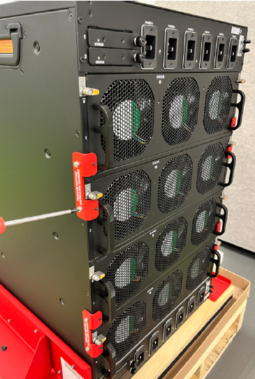
Place the empty chassis onto the shipping pallet.
-
Use a #2 Phillips screwdriver to secure the red pallet mount brackets to the chassis with 16 M4 x 10MM screws (eight screws per bracket).
Use 2.0 Newton-meters (18 inch-pounds) of torque on these screws.
Note: If red pallet mount brackets and silver fan tray stop bracket are already attached to the pallet, proceed to step 11. Otherwise, perform steps 9 through 10.
-
Use a 10mm socket to secure both brackets to the pallet with eight M6 X 20MM hex head screws (four screws per bracket).
Use 5.0 Newton-meters (44 inch-pounds) of torque on these screws.

Note: This image is of a CX410 chassis, but the application is similar for a CX1610 chassis.
-
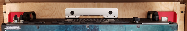
For a CX410 chassis, use a 10mm socket to secure the fan tray stop bracket to the pallet with two M6 X 20MM hex head screws.
Push bracket up against fan tray while tightening. Use 5.0 Newton-meters (44 inch-pounds) of torque on these screws.
-
For a CX1610 chassis, use a #2 Phillips screw driver to install the quantity (4) fan tray stop brackets with quantity (8) M4 X 10MM screws. Torque to 2.0 Newton-meters (18 inch-pounds). Push brackets up against fan trays while tightening.
-
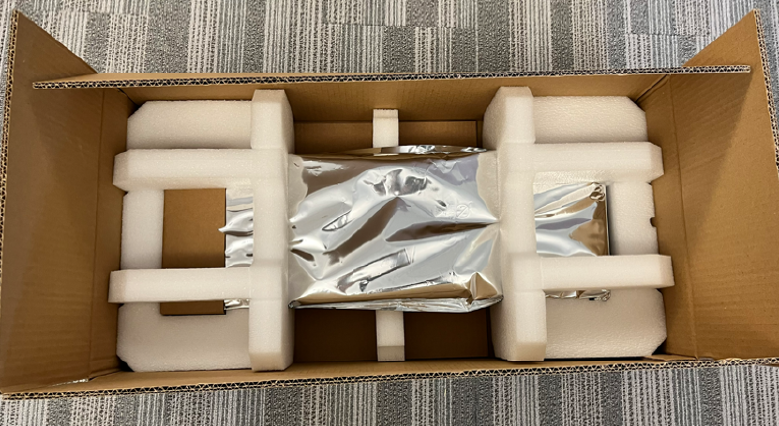
Place the ESD bag over the chassis, and then install the corrugated side panel assembly with the six corru clips inside the bottom tray.
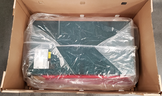
Note: This image is of a CX410 chassis, but the application is similar for a CX1610 chassis.
-
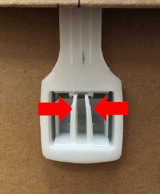
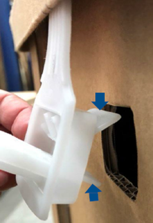
Install the corru clips by squeezing the clip as shown below, and then pulling out to unlock the clip.
-
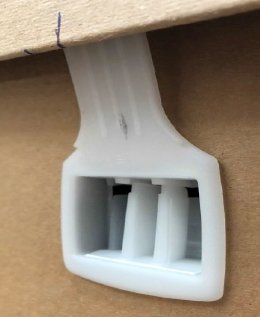
Secure the six corru clips by pushing the bottom tab into the slot, and then while keeping the clip open, push the top tab into the slot (three clips per side).
-
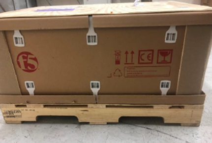
Secure the clip by pushing the clip flush to the corrugated sleeve, and then pushing the clip lever in until it clicks.
-
Place the two accessory trays on top of the chassis, if available.
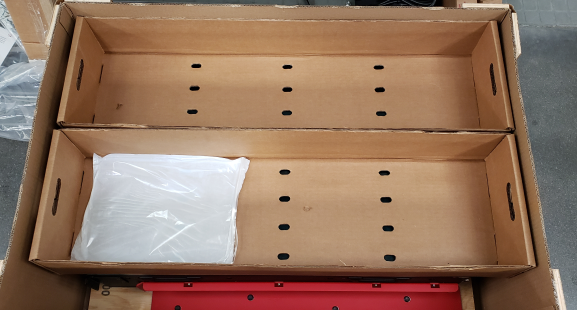
Note: This image is of a CX410 chassis, but the application is similar for a CX1610 chassis.
-
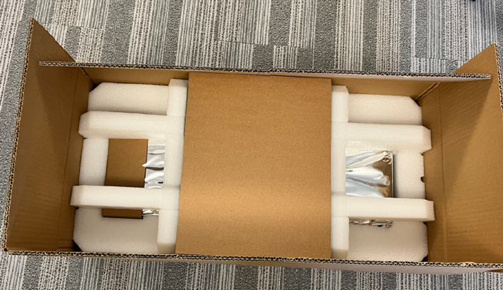
Place the lid on top over the corrugated side panel assembly, with the six corru clips on the outside.
Note: This image is of a CX410 chassis, but the application is similar for a CX1610 chassis.
If it becomes necessary to transport a blade to another location or return it to F5, these guidelines will help ensure that you repackage the blade properly.
You can perform a disk erase operation to erase all sensitive data from storage drives before you return a blade to F5. For more information, see F5 Platforms: Essentials at techdocs.f5.com/en-us/hw-platforms/f5-plat-hw-essentials.html.
Important: Before returning any equipment, contact F5 to obtain a Service Order (SO) or Return Material Authorization (RMA) case number.
Important: You must use shipping materials and packaging provided by F5 when repackaging the blade.
Note: Be sure to keep a record of the tracking number and ship date. These will be needed to track lost shipments.
Note: Do not include any cables, removable optical transceiver modules, GBICs, or other peripheral items if you are returning the blade to F5.
For information on installing your replacement blades in the chassis, see BX110/BX520 blade installation in a VELOS chassis in the “Platform Installation” section.
Important: Replacement blades provided by F5 do not come pre-installed with F5OS-C software.
Important: Before you physically remove a blade from the chassis, be sure to remove the blade/slot from any chassis partitions from either the system controller webUI or the CLI. For more information, see VELOS Systems: Administration and Configuration at the F5OS Knowledge Center.
VELOS BX110 Series and BX520 Series blades must be shipped in F5-provided packaging.
-
Disconnect all cables and remove any optical modules.
-
Press the blue latch release on the front of the blade to release the ejector handle.
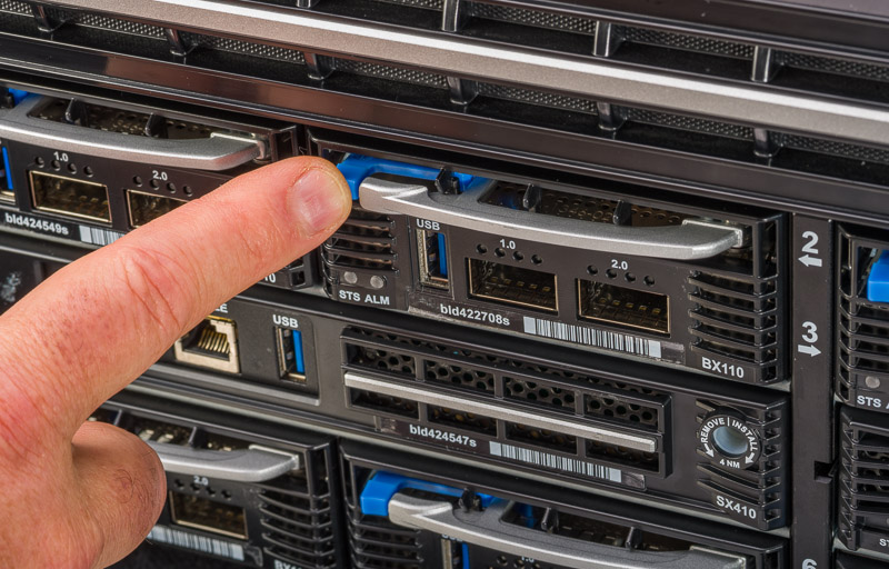
Note: This image is of a BX110 blade, but the application is similar for a BX520 blade.
-
Grasp the ejector handle and pull toward you, ensuring that you support the weight of the blade as you remove it from the chassis.
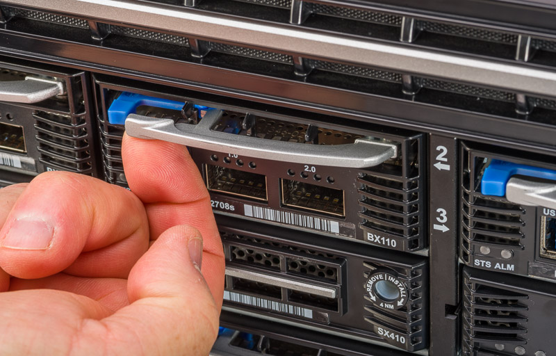
Note: This image is of a BX110 blade, but the application is similar for a BX520 blade.
-
For the BX110 blade, follow these steps:
-
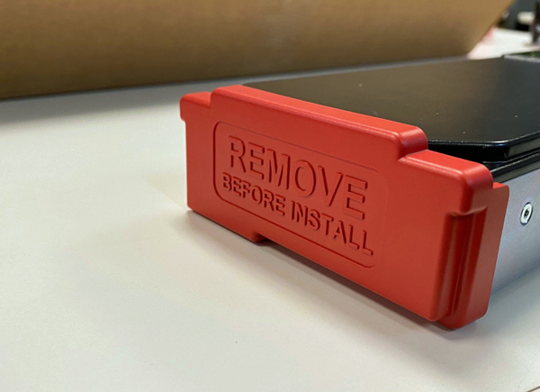
Install the red protective cap onto the back of the blade.
-
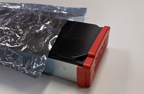
Place the blade into the antistatic bag.
-
Fold over the sides of the antistatic bag and use tape to close and secure the opening.
-
Fold over the excess at the two ends and then place the blade into the antistatic foam insert.
-
Place the foam box containing the blade into the blade box, and then place the antistatic foam pad on top of the blade.
-
Close the blade box and then insert the tabs into the slots.
-
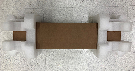
Slide the foam end caps onto each end of the blade box, and then place the blade box into the outer shipping box.
-
Close and seal the outer shipping box.
-
-
For the BX520 blade, follow these steps:
-
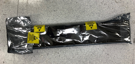
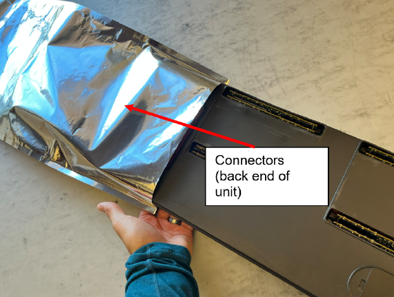
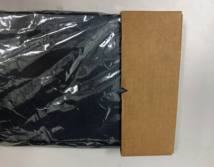
Place the blade into the ESD bag connector end first as shown.
-
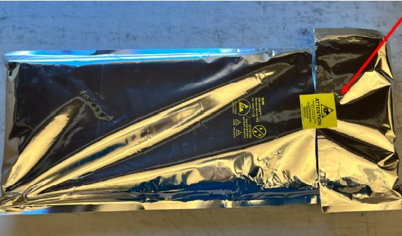
Flip the assembly over and seal the bag closed with tape.
-
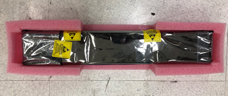
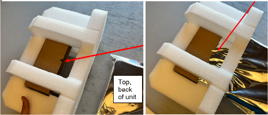
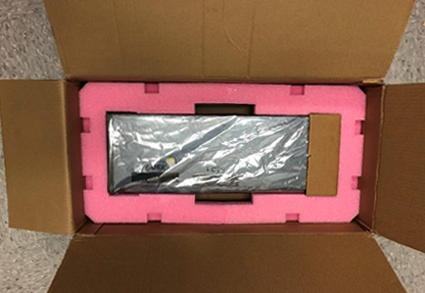
Flip the assembly over and place the rear foam support (with corrugated insert) onto the back of the unit with the notch facing upwards as shown.
-
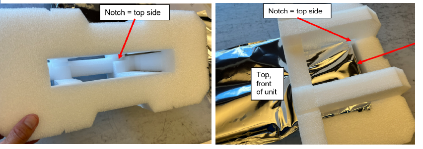
Install the front foam support (no corrugated insert). The notch in the foam should be on the top side of the unit as shown.
-
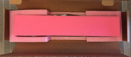
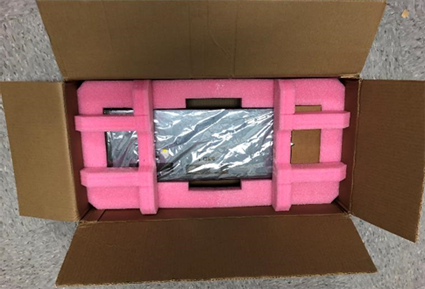
Place one of the middle foam supports into the box and install the unit as shown.
-
Install the top middle support and close and seal the box.
-
If you are not immediately installing a new blade into the empty slot, be sure to insert a blade blank into the empty slot.
Warning: Blade blanks or blades must be installed in all unused slots, as they help ensure proper airflow within the chassis and EMI compliance of the unit.
If it becomes necessary to transport a system controller to another location or return it to F5, these guidelines will help ensure that you repackage it properly.
You can perform a disk erase operation to erase all sensitive data from storage drives before you return a system controller to F5. For more information, see F5 Platforms: Essentials at techdocs.f5.com/en-us/hw-platforms/f5-plat-hw-essentials.html.
Important: Before returning any equipment, contact F5 to obtain a Service Order (SO) or Return Material Authorization (RMA) case number.
Important: You must use shipping materials and packaging provided by F5 when repackaging the system controller.
Note: Be sure to keep a record of the tracking number and ship date. These will be needed to track lost shipments.
Note: Do not include any cables, removable optical transceiver modules, GBICs, or other peripheral items if you are returning the system controller to F5.
VELOS SX410 Series system controllers must be shipped in F5-provided packaging.
-
Disconnect all cables and remove any optical modules.
-
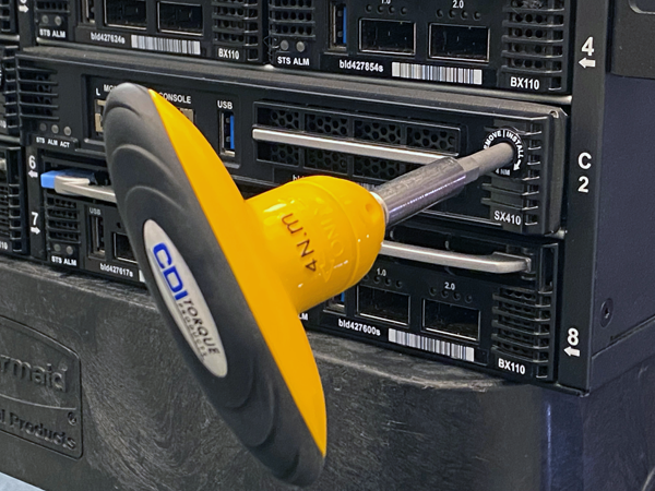
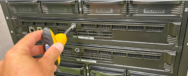
Insert the 4 Newton-meter T-handle 5mm hex torque wrench provided with the replacement system controller into the jackscrew receptacle and turn it counter-clockwise to eject the system controller.
The system controller slowly backs out of the chassis as you turn the jackscrew. Continue turning the torque wrench until the system controller ceases to move any further.
The SX410 system controller has the receptacle on the right side of the assembly.
The SX1610 system controller has the receptacle in the center of the assembly.
-
Grasp the front of the system controller and pull toward you to remove it from the chassis.
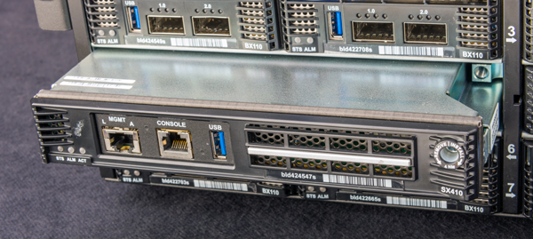
Note: On the SX410 system controller, the perimeter of the system controller should be pulled. On the SX1610 system controller, there are designated pull locations on the left and right.
-
Place the system controller into the antistatic bag.
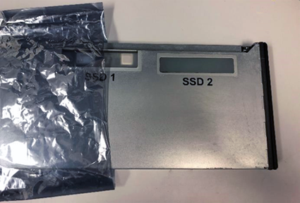
Note: This image is of an SX410 system controller, but the application is similar for an SX1610 system controller.
-
Flip over the antistatic bag, fold over the long side of the bad, and then use tape to close and secure the opening.
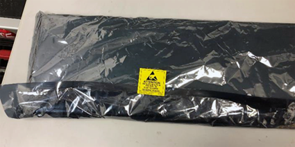
Note: This image is of an SX410 system controller, but the application is similar for an SX1610 system controller.
-
Fold over the open end of the bag, leaving some slack at the front and rear of the system controller, and then use tape to close and secure both folds.
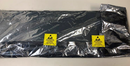
Note: This image is of an SX410 system controller, but the application is similar for an SX1610 system controller.
-
Flip the system controller top side up and then slide the end cap assembly onto the connector end of the controller, with the orientation notch on the end cap facing up.
Note: This image is of an SX410 system controller, but the application is similar for an SX1610 system controller.
-
Place the system controller into the antistatic foam insert.
Note: Antistatic foam might vary in color from what is shown.
Note: This image is of an SX410 system controller, but the application is similar for an SX1610 system controller.
-
Assemble the two top foam pieces and then place them on top of the system controller.
-
Close and seal the shipping box.