Updated Date: 07/08/2026
Platform Installation
After you have reviewed the hardware requirements and become familiar with the VELOS CX Series platform, you can install the platform into a rack. It is important that you install this platform in a secure area, with adequate ventilation and temperature control.
Warning: Due to the weight of the platform, it is recommended that you use a lift to transport and install the chassis. The lift handles on the chassis can support the weight of an empty chassis, but it is recommended to only use them to maneuver the chassis on and off of the lift. Manually lifting the chassis risks personal injury.
Important: Before you install this platform, review the environmental guidelines to make sure that you are installing the platform into a compatible rack and in the appropriate environment.
Important: Due to the larger size and weight of chassis platforms, F5 recommends that you install these platforms near the bottom of the rack.
Important: F5 strongly recommends that you install the chassis into a rack before you install any blades. This ensures that the weight of the chassis remains manageable as you install the chassis into a rack.
Note: After you install a blade, wait approximately one to two minutes before installing another to ensure that each blade has sufficient time to boot. When the Status LED is green, the blade is fully booted.
Note: F5 recommends that you keep all original packaging, in case you need to repackage and ship the platform later.
The AC-powered chassis includes all of the hardware components listed here.
|
Quantity |
Hardware |
|---|---|
|
2 (CX410) or 6 (CX1610) |
220V high-line input AC power cables (black). Might include multiple power cable types if product is delivered outside of the US/Canada. Note: This type of cable requires a NEMA 6-20R wall outlet or a region-specific equivalent. Region-specific power cables are available from F5. |
|
2 |
RJ45 to DB9 console port cable (beige) |
|
2 |
RJ45F to RJ45M rolled adapter (beige) |
|
1 |
Rack-mount rail kit (4 post kit is included, 2 post kit is orderable) |
|
1 |
Electrostatic discharge (ESD) wrist strap |
You will need to provide these hardware components when installing an AC-powered chassis.
| Quantity | Hardware |
|---|---|
| 1 (CX410) or 2 (CX1610) | 12 AWG copper grounding wire (color code insulation, as required) |
| 1 (CX410) or 2 (CX1610) | Dual ring ground terminal lug, with 0.63 inch (1.60 cm) spaced holes for 1/4" (6mm) studs. |
| 1 | Wire stripping tool |
| 1 | Crimping tool for the ground wire (if crimp-style lug is used) |
| 1 | #2 Phillips screwdriver |
The DC-powered chassis includes all of the hardware components listed here.
| Quantity | Hardware |
|---|---|
| 4 (CX410) or 12 (CX1610) | DC power supply connectors, standard DC power only (part number: CON-0536) |
| 2 | RJ45 to DB9 console port cable (beige) |
| 2 | RJ45F to RJ45M rolled adapter (beige) |
| 1 | Rack-mount rail kit (4 post kit is included, 2 post kit is orderable) |
| 1 | Electrostatic discharge (ESD) wrist strap |
You will need to provide these hardware components when installing a DC-powered chassis.
| Quantity | Hardware |
|---|---|
| 1 | Rack-mounted power disconnect |
| 8 (CX410) or 24 (CX1610) | 2 AWG copper wiring leads |
| 1 (CX410) or 2 (CX1610) | 2 AWG copper grounding wire (color code insulation, as required) |
| 1 (CX410) or 2 (CX1610) | Dual ring ground terminal lug, with 0.63 inch (1.60 cm) spaced holes for 1/4" (6mm) studs. |
| 1 | Wire stripping tool |
| 1 | Crimping tool for the ground wire (if crimp-style lug is used) |
| 1 | Screwdriver,T20 Torx drive (preferred) or flat-head |
| 1 | #2 Phillips screwdriver |
For each platform, you might need to provide additional peripheral hardware. If you plan to remotely administer the system, it would be helpful to have a workstation already connected to the same subnet as the management interface.
|
Type of hardware |
Description |
|---|---|
|
Network hubs, switches, or connectors to connect to the platform network interfaces |
You must provide networking devices that are compatible with the network interface ports on the platform. BX110 blades support 10GbE, 25GbE, 40GbE and 100GbE on ports 1.0 and 2.0. 10G requires a breakout cable from 40G. 25G requires a breakout cable from 100G. BX520 blades support 100GbE on port 1, and 400GbE on port 2. The system controller management port supports 10G, 1G, and 100M. Important: To support 25G on BX110 blades, you must use an IEEE compliant 25G Ethernet switch. |
|
USB flash drive |
You can use any USB-certified flash drive for installing upgrades and for system recovery. Important: When using a USB flash drive, verify that the drive is fully seated in the USB port. |
|
Management console or console server |
You can remotely manage the platform by connecting to a management console or console server through the console ports on the system controllers. The system controllers include a built-in terminal service that enables you to access blades using SSH.Important: In the event that network access is impaired or not yet configured, the serial console might be the only way to access the unit. You should perform all installations and upgrades from the serial console, as these procedures require reboots, in which network connectivity is lost temporarily. |
|
Management workstation that is routable to the management port |
You can use the default platform configuration if you have a management workstation set up. |
After you have reviewed the hardware requirements and become familiar with the VELOS CX Series platform, you can install the unit into a standard 19-inch rack, which can be either open or enclosed.
Warning: Due to the weight of the platform, it is recommended that you use a lift to transport and install the chassis. The lift handles on the chassis can support the weight of an empty chassis, but it is recommended to only use them to maneuver the chassis on and off of the lift. Manually lifting the chassis risks personal injury.
Important: Before you install this platform, review the environmental guidelines to make sure that you are installing the platform into a compatible rack and in the appropriate environment.
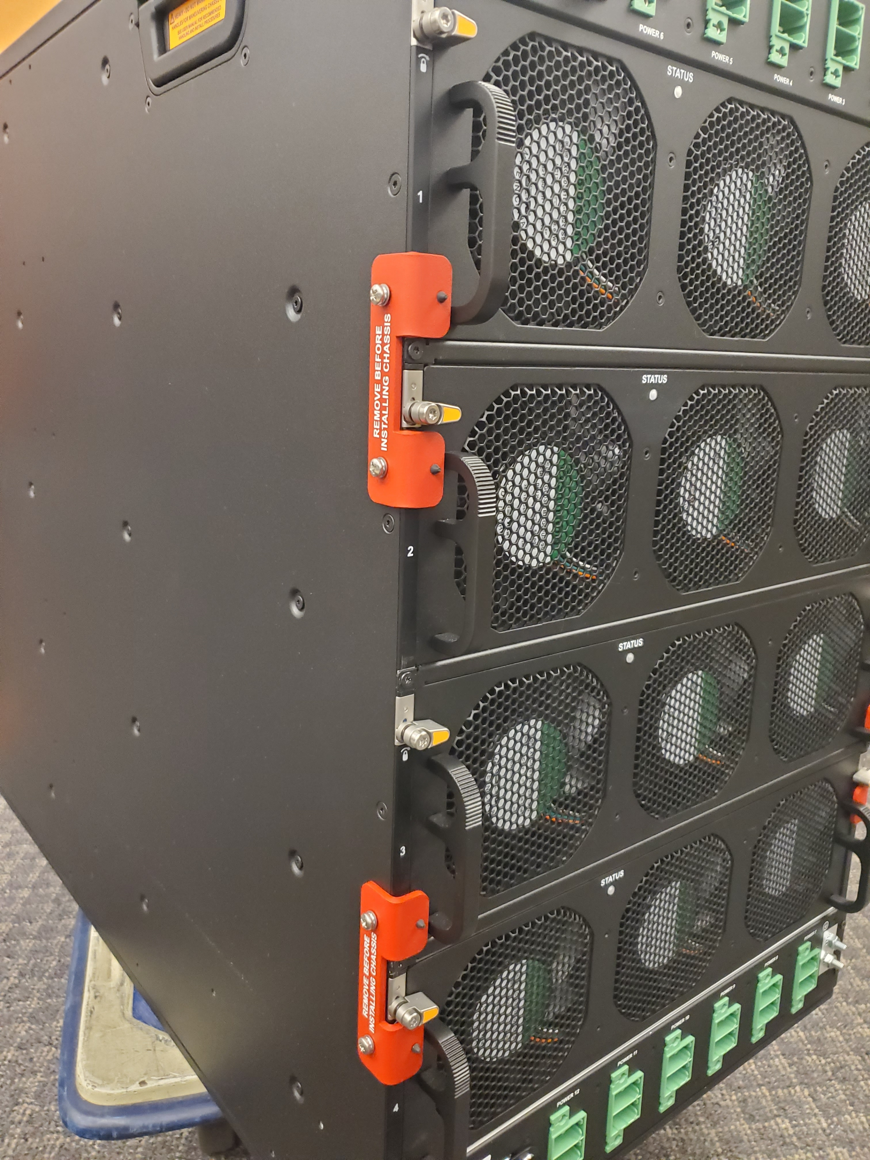
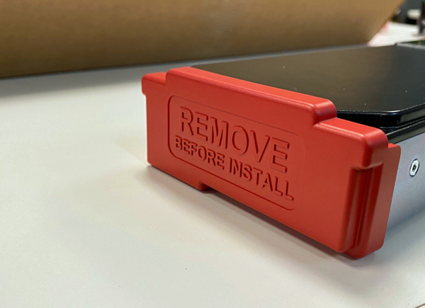
Important: Before you install this platform, make sure that you remove the red fan tray retention brackets and retain them for repackaging purposes.
The included rack-mount rail kits are compatible with four-post EIA racks measuring 28 inches to 40 inches deep. The rail assemblies use a spring action design that enables you to easily install into either square, round untapped, or tapped mounting holes.
Detailed instructions for installing the rack-mount rail kit are included in the kit hardware by the manufacturer.
Important: Be sure to follow steps 5 and 6 from the rack-mount rail kit detailed instructions to ensure that the rail assemblies are fully secured to the rack.
When you are installing using the rack-mount rail kit, use these components.
| Quantity | Hardware |
|---|---|
| 1 | Fixed rail assembly (left hand) |
| 1 | Fixed rail assembly (right hand) |
| 8 | #8-32 x .38 inch flat-head screws, Phillips |
| 8 | #8-32 x .38 inch pan-head screws, Phillips |
| 8 | Conical washer adapter |
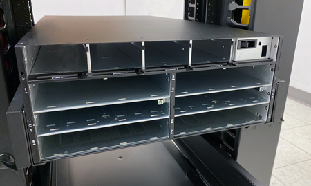
Before you install the chassis into a four-post rack, verify that the rail assembles and chassis rack stop brackets are securely installed.
You need to secure the chassis to the rack using rack manufacturer-provided screws before you install blades. You can choose to remove the fan trays and power supplies to make the chassis lighter for installation.
Warning: Due to the weight of the platform, it is recommended that you use a lift to transport and install the chassis. The lift handles on the chassis can support the weight of an empty chassis, but it is recommended to only use them to maneuver the chassis on and off of the lift. Manually lifting the chassis risks personal injury.
Important: Before you install this platform, review the environmental guidelines to make sure that you are installing the platform into a compatible rack and in the appropriate environment.
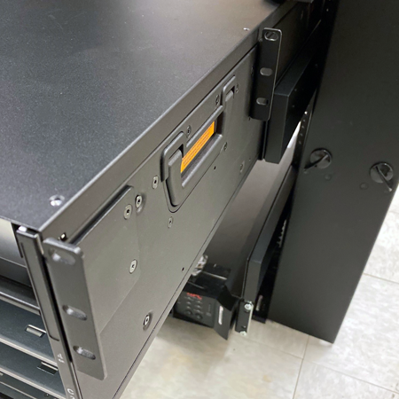
-
Use a lift device to lift and hold the chassis in place during installation as you slide back until the rack stop brackets touch the rack.
-
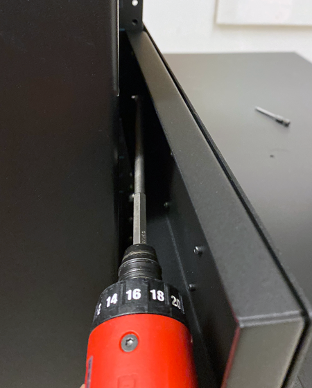
With the chassis held in place on the rack, install at least three (3) rack-manufacturer provided screws to each rack stop bracket to secure the chassis into place. The CX1610 chassis requires at least six (6) screws per side to fasten the stop brackets to the rack.
Torque per the rack manufacturer’s specification.
The image is of a CX410 chassis, but the application is similar for a CX1610 chassis.
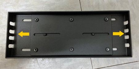
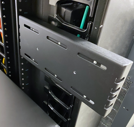
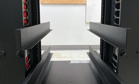
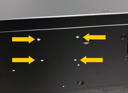
For installing into two-post racks, you use the two-post rack mount shelf kit. You also need to install the included chassis rack stop brackets to the mid-chassis mount locations.
Important: For NEBS installations into two-post racks, you must secure the chassis to the rack at the mid-chassis mount locations.
Before you install the chassis into a two-post rack, verify that the two-post rack mount shelf and chassis rack stop brackets are securely installed.
You will need these tools to install the two-post rack and secure the chassis:
- #2 Phillips head bit and torque driver rated for at least 2.0 Newton-meters (18 inch-pounds)
You need to install the chassis before you install blades. You can choose to remove the fan trays and power supplies to make the chassis lighter for installation.
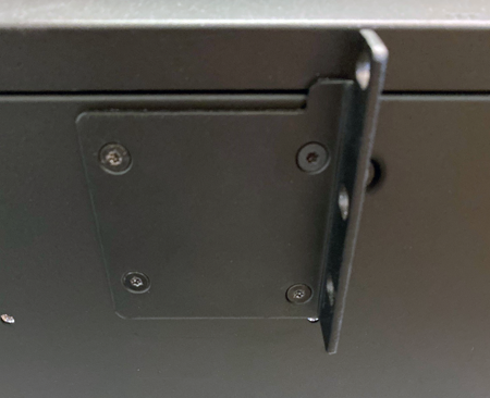
-
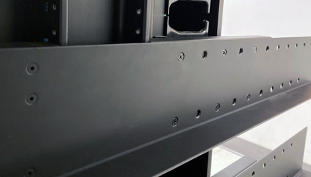
Remove the rear support from the assembly by removing the two (2) flathead screws.
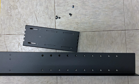
-
Verify that you can slide the nut plate within the rear support.
-
Install the rear support assembly to the rear of the rack and secure it with at least two (2) screws. The CX1610 chassis requires at least six (6) screws per side to fasten the stop brackets to the rack.
Note: The brackets are symmetrical, and you can mount either end to the rack.
Use slots that are not adjacent to each other. Tighten screws to the rack manufacturer’s recommended torque.
Tip: You can use “tacky wax” to hold the screw to the driver while you are positioning the screw.
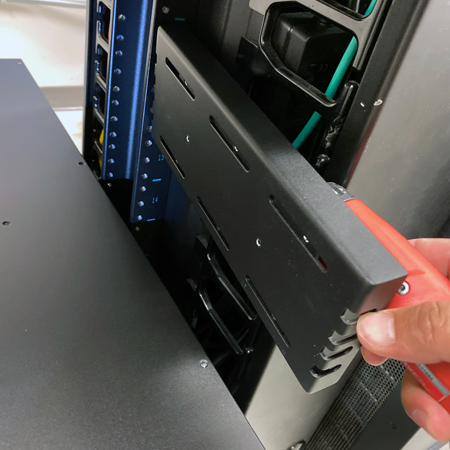
-
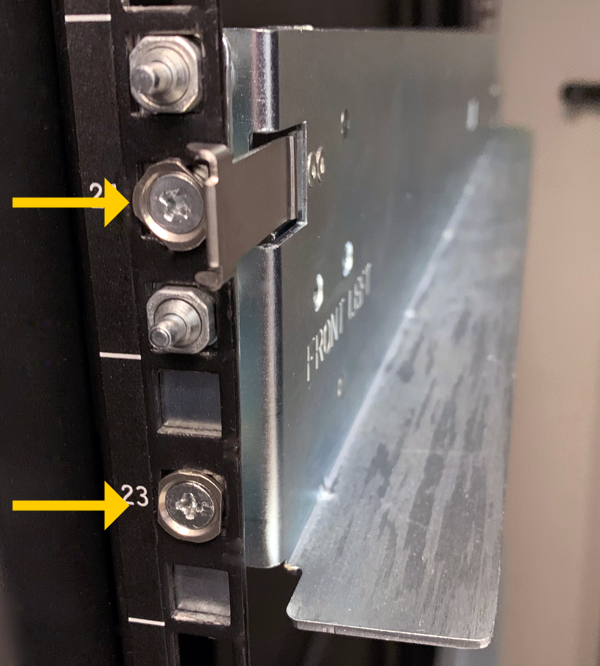
Position the main assembly so that the front support is flush to the rack post.
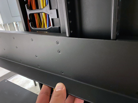
-
With the front support in position, slide the nut plate so that the nuts line up with the countersink holes.
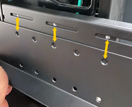
-
Use two screws to hold the main assembly in position.
Use 2.0 Newton-meters (18 inch-pounds) of torque on these screws.
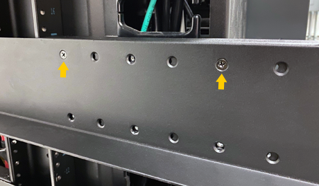
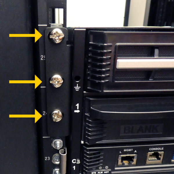
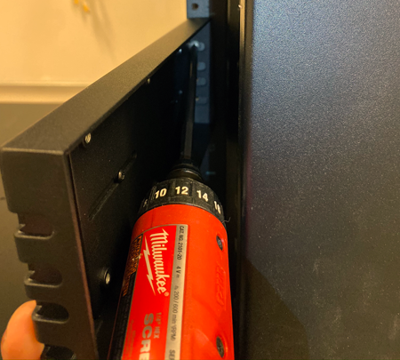
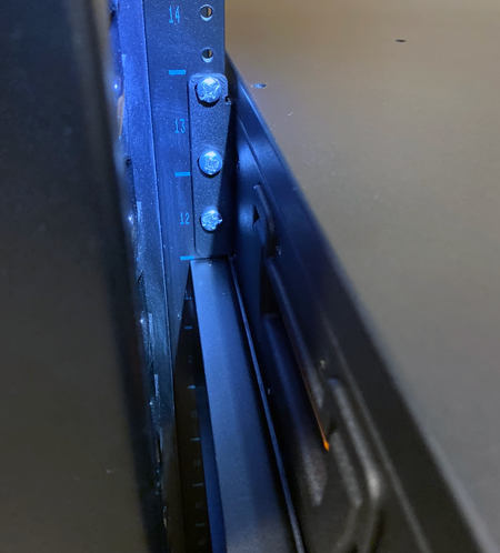
-
Use at least two screws to secure the front support to the rack.
Use slots that are not adjacent to each other. Tighten screws to the rack manufacturer’s recommended torque.
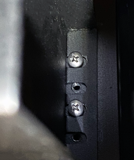
-
Install the remaining four flathead screws into the rear support using the included hardware.
Use 2.0 Newton-meters (18 inch-pounds) of torque on these screws.
-
Repeat steps 1-8 to install an assembly to the other side of the rack.
-
Install the chassis rack stop brackets to the mid-mount position on the left and right sides of the chassis using the included hardware.
Use 2.0 Newton-meters (18 inch-pounds) of torque on these screws.
-
Use a lift device to lift and hold the chassis in place during installation and slide the chassis back until the chassis rack stop brackets touch the rack.
-
With the chassis held in place on the rack, install three rack-manufacturer provided screws to each rack stop bracket to secure the chassis into place.
Tighten screws to the rack manufacturer’s recommended torque.
The chassis is now secured to your two-post rack. You can now reinstall all components into the chassis, as needed.
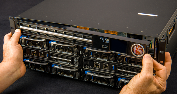
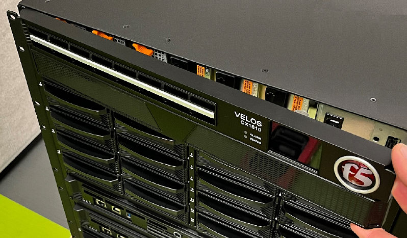
The front bezel with LCD touchscreen on the VELOS chassis is detachable. You can remove the bezel to access the power supply units (PSUs).
Important: This product is sensitive to electrostatic discharge (ESD). F5 recommends that you use proper ESD grounding procedures and equipment when you install or maintain the unit, including attaching a ground strap to the ground strap receptacle location on the front left side of the chassis.
The front bezel with LCD touchscreen is not pre-installed on your VELOS chassis, so you should install it before you can use the system.
Note: All photos shown are examples. The appearance of your components or accessories might vary slightly.
-
Pick up the front bezel using the indentations provided.
-
Align the metal tab(s) on the back left side of the replacement bezel with the corresponding cutout(s) on the left side of the chassis, and then rotate the right hand side of the bezel toward the chassis.
-
Press in on the right side until the bezel snaps into place and is secured to the chassis.
CAUTION:
Avoid pinching fingers when installing bezel.
Damage from electrostatic discharge (ESD) can occur if you do not use proper ESD grounding procedures and equipment when installing or performing maintenance on chassis components. F5 provides an ESD wrist strap with VELOS blades and system controllers for you to use when installing and maintaining blades and chassis components.
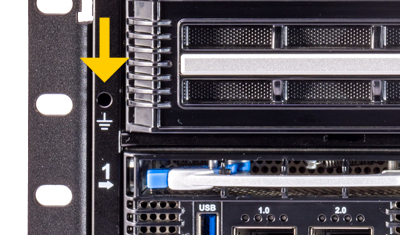
When installing or maintaining blades or chassis components, be sure to use an electrostatic discharge (ESD) wrist strap to help prevent damage to your system from ESD.
-
Place the wrist strap over your wrist and tighten the strap to make sure it has good contact with your bare skin.
-
Grasp the banana plug attached to the end of the strap and insert it into the wrist strap ground location on the chassis.
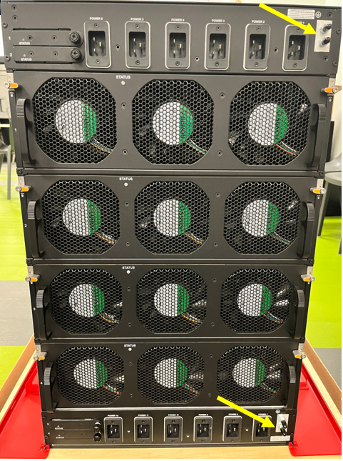
You must ground the chassis after you install it in a rack. The chassis ground lug is located on the back of the chassis.
Do not secure multiple bonding or grounding connectors with the same bolt. The grounding connectors do not need to be removed to perform service or installation procedures. You can connect other bonding or grounding conductors to a grounding connector provided a reliable bond between the connector and the equipment is not disturbed during installation, service, or maintenance of the platform.
The AC-powered platform requires a two-hole, 1/4 inch stud hole, .63 inch hole spacing ground lug. The tongue should be a maximum of .7 inches wide x 1.4 inches long. Minimum wire size is #12 AWG wire, though common lugs of this size are compatible with #2 AWG (an example is Panduit part number LCCX2-14A-E).
The DC-powered platform requires a two-hole, 1/4 inch stud hole, .63 inch hole spacing ground lug. The tongue should be a maximum of .7 inches wide x 1.4 inches long. Minimum wire size is #2 AWG wire (an example is Panduit part number LCCX2-14A-E).
Important: All grounding cable terminal lugs must meet appropriate safety standards.
Note: The platform must be grounded to a common bonding network (CBN).
Note: You should coat bare conductors with an appropriate antioxidant compound before you make crimp connections. You should bring all unplated connectors, braided strap, and bus bars to a bright finish and then coat them with an antioxidant before you connect them.
You must provide these components to properly ground the chassis:
- Crimping tool
- Wire stripping tool
- Dual ring ground terminal lug (such as, Panduit compression connector lug, part number: LCCX2-14A-L)
- For AC-powered chassis: one 12 AWG copper grounding wire long enough to reach from the chassis to the common bonding network (CBN)
- For DC-powered chassis: one 2 AWG copper grounding wire long enough to reach from the chassis to the common bonding network (CBN)
After the unit is installed in the rack and before you provide power to the system, you need to connect the grounding hardware.
-
Use the wire stripping tool to remove insulation as specified by the connector’s manufacturer from the end of the copper grounding wire.
-
Insert the stripped end of the copper grounding wire into the open end of the ground terminal lug until the wire stops.
-
Crimp the barrel of the ground terminal lug and verify that the wire is securely attached to the ground terminal.
-
Remove the M6 Keps nuts from the ground lug on the back of the chassis.
-
Install the ground terminal lug onto the chassis ground terminals.
-
Secure the ground terminal lug with the M6 Keps nuts.
Use 35 to 40 inch-pounds (4.0 TO 4.5 Newton-meters) of torque on these Keps nuts.
-
Connect the ground wire to a common bonding network (CBN).
The VELOS CX410 AC-powered chassis ships with two (2) power cords that you must use with the installed power supplies to connect the chassis to site power. The base system includes two (2) power supplies, but the chassis supports up to four (4) power supplies.
The VELOS CX1610 Series AC-powered chassis ships with six (6) power cords that you must use with the installed power supplies to connect the chassis to site power. The base system includes six (6) power supplies, but the chassis supports up to 12 power supplies.
Important: Do not use any cords other than those specifically designed for the VELOS chassis.
CAUTION:
The power supply unit (PSU) cord is used as the main disconnect device, ensure that the socket-outlet is located or installed near the equipment and is easily accessible.
Avertissement : Le cordon d’alimentation est utilisé comme interrupteur général. La prise de courant doit être située ou installée à proximité de l’équipement et être facile d’accès.
CAUTION:
This unit has more than one power supply unit (PSU) cord. Disconnect all PSU cords before servicing to avoid electric shock.
Avertissement : Cet appareil comporte plus d’un cordon d’alimentation. Afin de prévenir les chocs électriques, débrancher les deux cordons d’alimentation avant de faire le dépannage.
You can connect the power cables to the chassis after you install it in a rack.
-
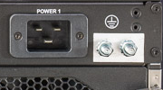
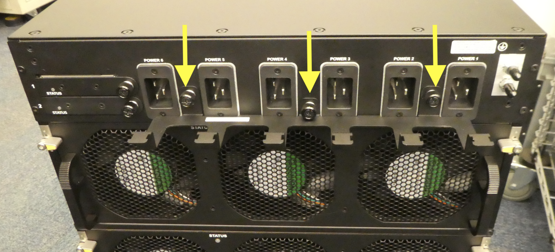
On the back of the chassis, locate the power outlets that correspond to the locations of the power supplies.
Each outlet is labeled to ensure that you connect each power cord to the appropriate outlet.
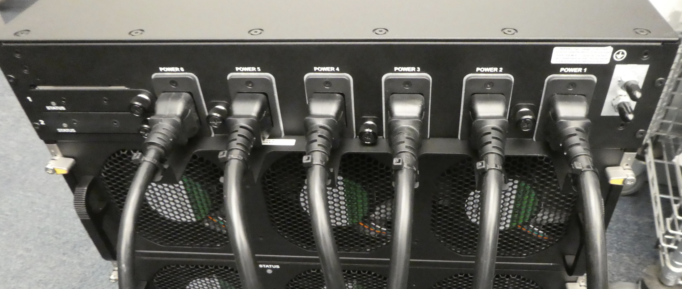
-
Attach the power cord to the outlet until it is firmly seated.
-
Plug the power cord into an approved power source.
-
Repeat this process for each power supply in the chassis.
-
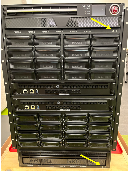
Verify that the LEDs on the front of the installed power supplies are lit to ensure that they are powered properly.
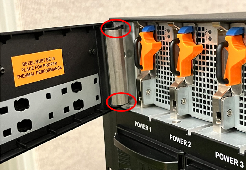
The power supplies are located under the removable bezel(s) on the front of the chassis.
Note: For the CX1610 chassis, there are additional power supply locations under the removable bottom bezel.
Note: For the CX1610 chassis, an optional cable restraints are available for the AC power cords that are included. This restraint bracket can be easily attached with captive fasteners at three designated points, providing a secure and organized method for securing the cords with zip ties (zip ties not included).
If you ordered a DC-powered chassis, your VELOS CX Series chassis comes pre-installed with DC power supplies.
Before you power this VELOS DC-powered platform, see Guidelines for DC-powered equipmentand Guidelines for NEBS platforms.
Note: You should coat bare conductors with an appropriate antioxidant compound before you make crimp connections. You should bring all unplated connectors, braided strap, and bus bars to a bright finish and then coat them with an antioxidant before you connect them.
You will need these tools to assemble and wire the DC connector plug:
- Wire stripping tool
- T20 Torx driver
Important: Be sure that the DC power source is off and the ground lug is connected to the ground terminal before you connect the platform to the DC power source.
After the platform is installed in a rack, you can connect the platform to the DC power source. When you connect the DC power source, you should also follow the safety requirements defined for your network operations center (NOC).
Important: Although the CX410 chassis ships with only two (2) power supply units (PSUs), the chassis includes four (4) terminal blocks. F5 recommends that you install all four (4) connector plugs upon initial setup.
Important: Although the CX1610 chassis ships with only six (6) power supply units (PSUs), the chassis includes 12 terminal blocks. F5 recommends that you install all 12 connector plugs upon initial setup.
-
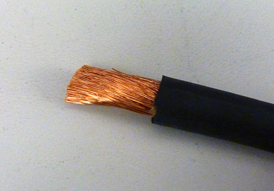
Review the DC power supply label and determine the correct wire size for your installation.
-
Strip approximately 0.75 inches (19 mm) of insulation off of each positive and negative wire where you connect the wire to the connector plug.
Repeat for each of the plugs.
-
Use a T20 Torx driver to torque the screw to 22-40 inch-pounds (2.5-4.5 Newton-meters).
Repeat for each of the four plugs.
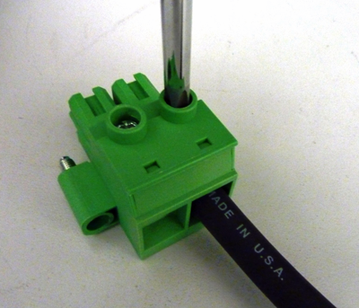
-
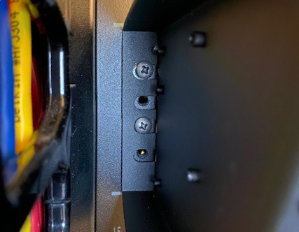
Connect the negative DC power lead to the -48V terminal on the connector plug.
This is labeled on the chassis.
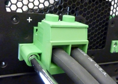
Note: This image is from a CX410 chassis, but the application is similar for a CX1610 chassis.
-
Connect the positive DC power lead to the +48V terminal on the connector plug.
This is labeled on the chassis.
-
Plug the connectors into the backplane connectors and secure them by tightening the two screws on each connector.
Torque to 22-40 inch-pounds (2.5-4.5 Newton-meters).
-
Repeat this process for each power supply in the chassis.
-
Power on the DC power source.
The system should begin to boot.
-
Verify that the LEDs on the front of the installed power supplies are lit to ensure that they are powered properly.
The power supplies are located under the removable bezel(s) on the front of the chassis.
After you have installed the unit into the rack, connect the cables and other hardware.
Important: In the event that network access is impaired or not yet configured, the serial console might be the only way to access the unit. You should perform all installations and upgrades from the serial console, as these procedures require reboots, in which network connectivity is lost temporarily.
-
If you are using the default network configured on the management interface, connect an Ethernet cable to the management port on both system controllers installed in the chassis.
Note: For EMI compliance, shielded cables are required for the management port, and the shield must be grounded at both ends.
-
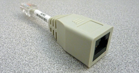
Connect the console port to a management console or console server. Depending on the console network to which you are attaching, you can use either the supplied RJ45 to DB9 console port cable or the RJ45F to RJ45M rolled serial adapter to connect the system controllers to a serial console server.
-
Connect a RJ45 to DB9 console port cable to the console port on each system controller.
Note: The default baud rate and serial port configuration is 19200/8-N-1.
-
Connect the RJ45F to RJ45M rolled serial adapter to the console port if you are connecting the system to a serial console server with a standard CAT5 cable, and then connect the CAT5 cable to the adapter. The adapter provides the appropriate pinout connection to your equipment. For information about cable and connector pinout specifications, see F5 Platforms: Accessories .
-
-
Connect power to installed power supplies:
Note: Be sure to route the power cords away from the fan tray so that the cords do not impede access to it.
- For AC-powered systems, connect a power cable to the power input panel on all installed power supplies, and then connect the cable to the power source.
- For DC-powered systems, attach an assembled DC terminal block to all installed power supply units and then connect the cables to your DC mains power source.
-
Connect any optical transceiver modules to your blades.
-
Remove the protective film from the LCD touchscreen using the small cutout on the lower right corner of the film.
You can now assign a management IP address to the system and then license the system.
Optionally, you should run the QKView utility. This utility collects configuration and diagnostic information about your system into a single file that you can provide to F5 Technical Support to aid in troubleshooting. For more information, see VELOS Systems: Supportability.
Blade support matrix for CX410 and CX1610 chassis
| Chassis | Blade support (BX110) | Blade support (BX520) |
|---|---|---|
| CX410 | Yes | - |
| CX410 | - | Yes |
| CX410 | Yes | Yes |
| CX1610 | - | Yes |
You can install up to eight BX110 or four BX520 blades in a VELOS CX410 Series chassis or up to 16 BX520 blades in a VELOS CX1610 Series chassis.
When you initially receive the chassis, the slots that can contain these blades are filled with blanks. A blank must be installed in each empty slot to ensure proper thermal management and regulatory compliance. To add a new blade, you first remove the blank from the corresponding slot and then insert the blade. Be sure to keep the blanks in case you need to change the blade configuration later. You should not operate the chassis for an extended period of time without all slots populated.
Note: For installation of a BX520 blade, a latch catch must be removed.
Important: This product is sensitive to electrostatic discharge (ESD). F5 recommends that you use proper ESD grounding procedures and equipment when you install or maintain the unit, including attaching a ground strap to the ground strap receptacle location on the front left side of the chassis.
If you are installing replacement blades from F5 after a Return Material Authorization (RMA), you will need to manually install software, since replacement blades provided by F5 do not come pre-installed with F5OS-C software. For more information on software installation, see the “Clean Installation” section in VELOS Systems: Software Installation and Upgrade at Documentation - F5OS-C and VELOS.
If a blank is installed in the slot where you want to install a blade, you must remove it. If the slot does not contain a blank, you can skip this procedure. F5 recommends that you store blanks in a safe place for later use.
-
Select the slot in which you want to insert a blade.
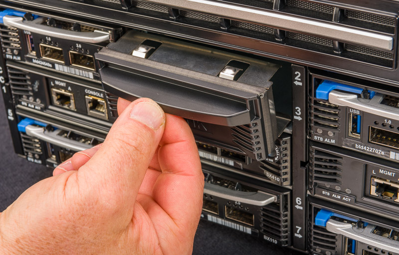
-
Grasp the handle and pull toward you to remove the blade blank.
-
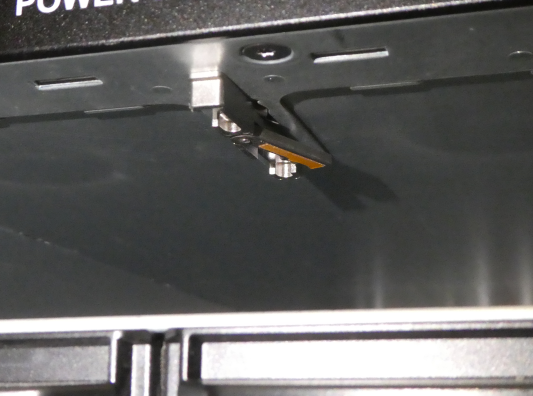
Remove the bay center latch catch from the chassis by rotating it counterclockwise. See the instructions included with the chassis.
Important: The CX410 and CX1610 chassis comes configured with a latch catch for each bay slot. The BX520 uses two slots in the bay and the center latch will need to be removed for this blade.

-
Before you install the BX520 unit, remove the bay center latch catch from the chassis.
-
To remove, rotate the handle counterclockwise.
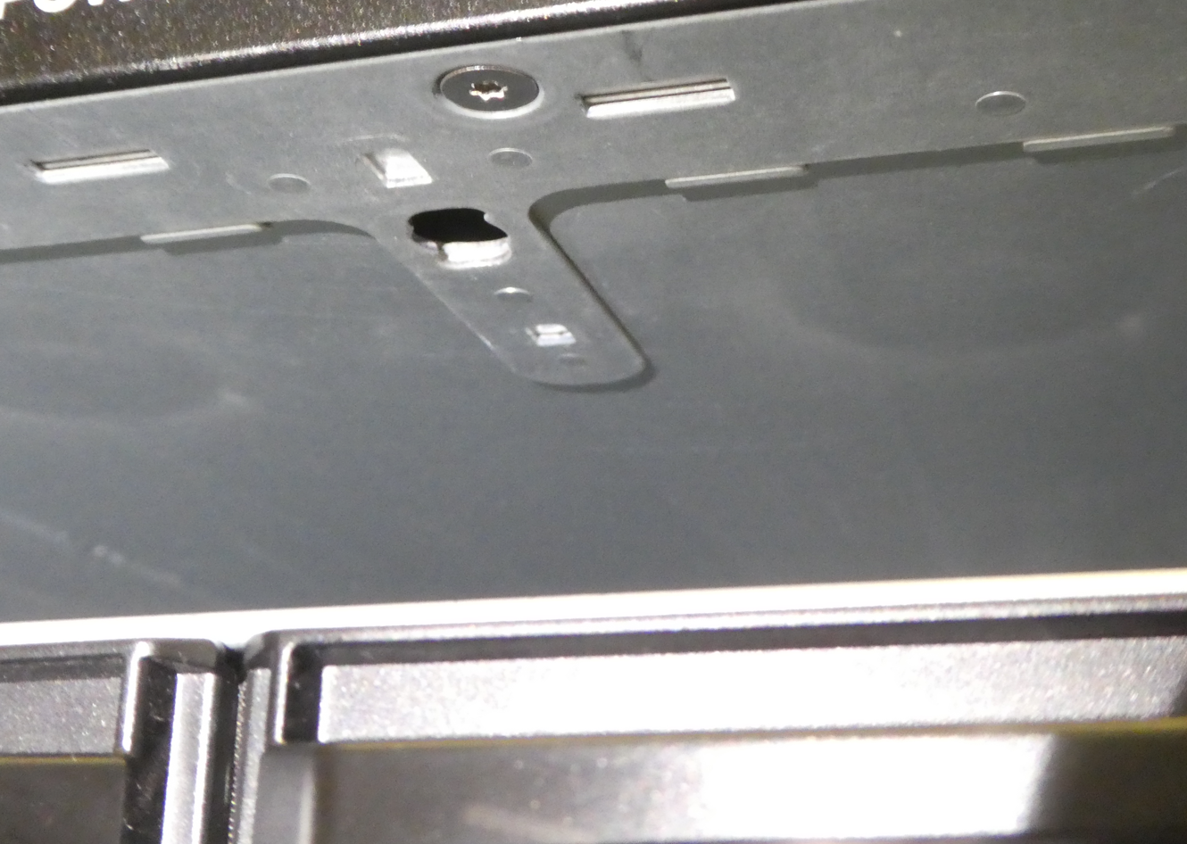
-
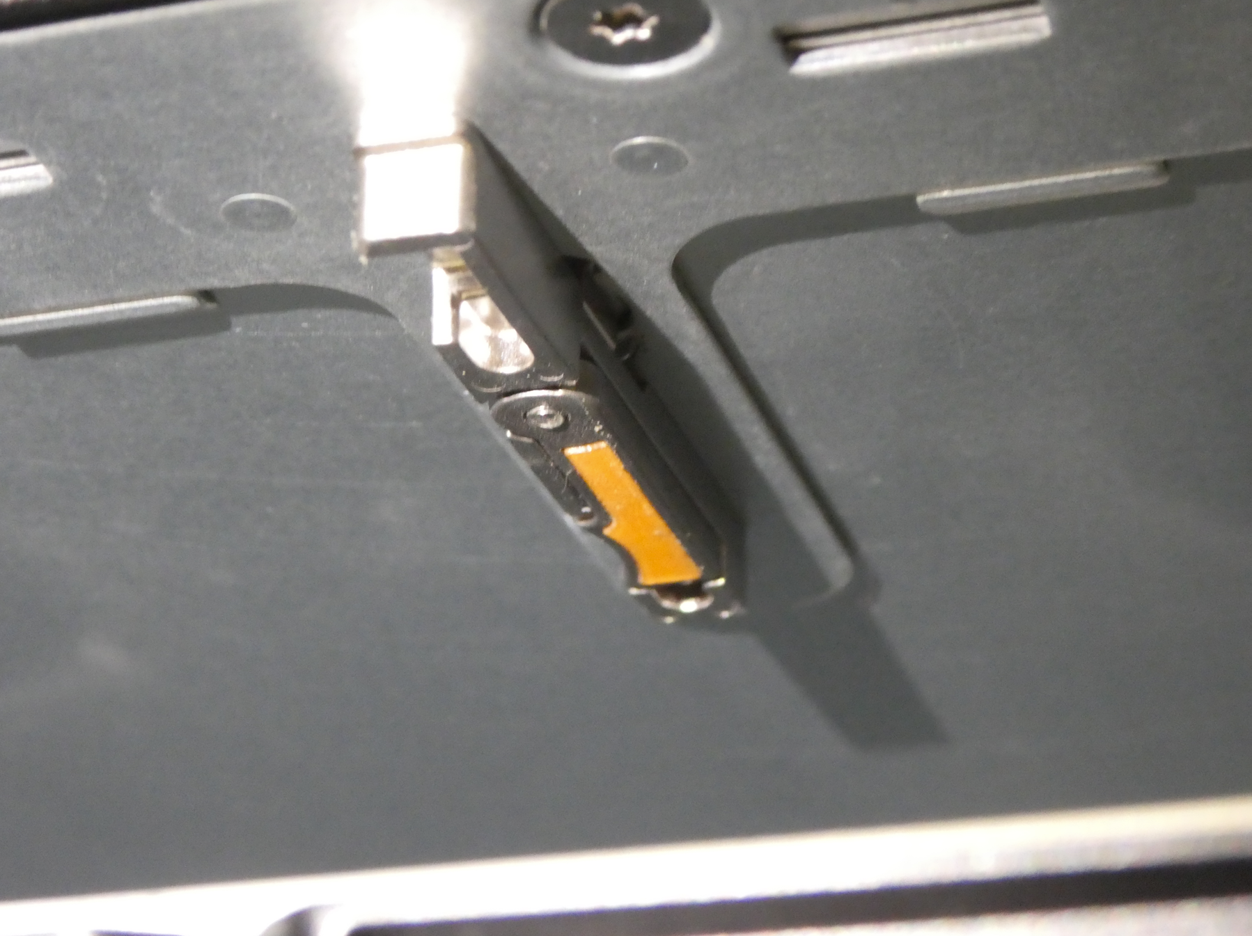
Remove the latch from the assembly.
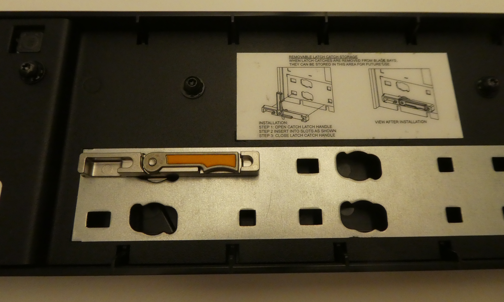
-
Install the latch catch bracket onto the back side of the LCD assembly in one of the storage locations provided. See the image below for an example location.
Check if a blank is in the slot in which you want to install a blade. If so, you must first remove it.
You can install a blade in the chassis without powering down the system.
-
Remove the protective cap, if there is one, from the back of the blade.
-
Carefully slide the blade into the slot.
-
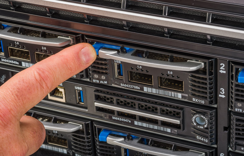
Before the blade is fully seated, press the blue latch release on the front of the blade to release the ejector handle.
Note: If the handle does not pop out, pull out on the blade until it does.
-
Slide the blade in until the ejector contacts the catch inside the chassis.
-
Press the silver ejector handle until the blade is locked in place.
-
Repeat this process with each blade until all blades are secured in the unit.
Note: After you install a blade, wait approximately one to two minutes before installing another to ensure that each blade has sufficient time to boot. When the Status LED is green, the blade is fully booted.
Important: Before you physically remove a blade from the chassis, be sure to remove the blade/slot from any chassis partitions from either the system controller webUI or the CLI. For more information, see VELOS Systems: Administration and Configuration at the F5OS Knowledge Center.
You can remove a blade from the chassis without powering down the system.
-
Identify the blade that you would like to remove from the chassis.
The chassis supports blade hot swap, but optionally, you can choose to halt the blade at the command line interface (CLI).
-
Disconnect all cables and remove any optical modules.
-
Press the blue latch release on the front of the blade to release the ejector handle.
Note: This image is of a BX110 blade, but the application is similar for a BX520 blade.
-
Grasp the ejector handle and pull toward you, ensuring that you support the weight of the blade as you remove it from the chassis.
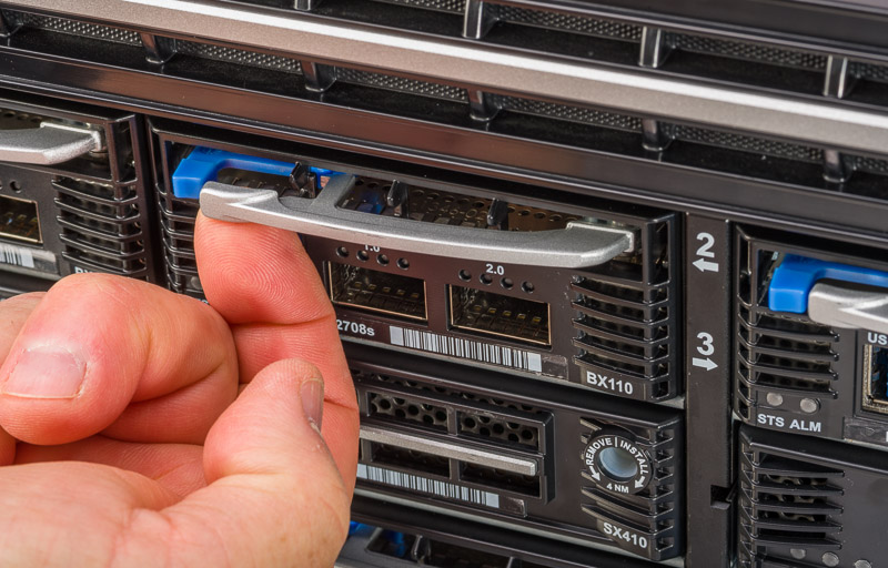
Note: This image is of a BX110 blade, but the application is similar for a BX520 blade.
If you are not immediately installing a new blade into the empty slot, be sure to insert a blade blank into the empty slot.
Warning: Blade blanks or blades must be installed in all unused slots, as they help ensure proper airflow within the chassis and EMI compliance of the unit.
You can manage yourVELOS platform by connecting to the active system controller in your system using the floating IP address. The system supports configuring management addresses in both IPv4 and IPv6 formats.
Important: Even if you use DHCP to configure other management IP addresses for your system, you must manually configure the floating IP address.
With VELOS platforms, you can either manually assign or use DHCP to assign management IP addresses on a per-system controller basis. Initially, all blades installed in the chassis belong to a single default chassis partition, which you can access using a partition management IP address. The partition IP address enables you to access the system to configure other aspects of the product, such as the VLANs, link aggregation, and so on.
A blade within a cluster is also known as a slot. Each slot must be assigned to a chassis partition, and slots are initially assigned to a default partition.
You can manage your system using these methods:
- CLI
- webUI
- Rest API
For information on licensing, administering, and configuring your VELOS system, see VELOS Systems: Administration and Configuration at Documentation - F5OS-C and VELOS.
After you connect your system controllers to a management console or console server, you can configure a floating management IP address and individual management IP addresses for both system controllers from the system controller CLI. You can use either IPv4 or IPv6 format for these IP addresses.
-
Connect to the system using a management console or console server.
Note: The default baud rate and serial port configuration is 19200/8-N-1.
-
Log in to the command line interface (CLI) of the system controller using an account with admin access.
When you log in to the system, you are in user (operational) mode.
-
Change to config mode.
configThe CLI prompt changes to include
(config). -
Configure the management IP address for controller-1.
system mgmt-ip config [ipv4 | ipv6] controller-1 address <*ip-address*>This example assigns an IPv4 address:
syscon-1-active(config)# system mgmt-ip config ipv4 controller-1 address 192.0.2.10This example assigns an IPv6 address:
syscon-1-active(config)# system mgmt-ip config ipv6 controller-1 address 2001:db8:ffff:100::1 -
Configure the management IP address for controller-2.
system mgmt-ip config [ipv4 | ipv6] controller-2 address <*ip-address*>This example assigns an IPv4 address:
syscon-1-active(config)# system mgmt-ip config ipv4 controller-2 address 192.0.2.11This example assigns an IPv6 address:
syscon-1-active(config)# system mgmt-ip config ipv6 controller-2 address 2001:db8:ffff:101::1 -
Configure the floating IP address for the system controllers.
system mgmt-ip config [ipv4 | ipv6] floating <*ip-address*>This example assigns an IPv4 address:
syscon-1-active(config)# system mgmt-ip config ipv4 floating 192.0.2.15This example assigns an IPv6 address:
syscon-1-active(config)# system mgmt-ip config ipv6 floating 2001:db8:ffff:102::1 -
Configure the default gateway, if not using DHCP.
system mgmt-ip config [ipv4 | ipv6] gateway <*gateway-ip*>This example assigns an IPv4 gateway:
syscon-1-active(config)# system mgmt-ip ipv4 gateway 192.0.2.254This example assigns an IPv6 gateway:
syscon-1-active(config)# system mgmt-ip ipv6 gateway 2001:db8:ffff:100::fffe -
Configure the default CIDR prefix length.
system mgmt-ip config [ipv4 | ipv6] prefix-length <*prefix-length*>This example assigns a prefix length for an IPv4a address:
syscon-1-active(config)# system mgmt-ip ipv4 prefix-length 24This example assigns a prefix length for an IPv6 address:
syscon-1-active(config)# system mgmt-ip ipv6 prefix-length 64 -
Commit the configuration changes.
commit
The system saves the new IP addresses and gateway address for your system controllers. You can now use the floating IP address that you assigned to access the system either over SSH or using the webUI. The floating IP address will always be available on the primary system controller.