Updated Date: 07/07/2026
F5 VELOS system initial configuration
The Setup wizard is available to assist you in setting up basic management networking for the system controllers on the VELOS system. You can choose to enable DHCP and have your IP address settings configured automatically, or disable DHCP and manually configure your IP address settings.
After you have configured network settings using the Setup wizard, you can use the VELOS webUI to perform additional configuration of your system, including:
- Running the Setup wizard
- Logging in to the system controllerwebUI
- Licensing the system
- Editing the default chassis partition
- Creating required VLANs
- Importing a tenant image
- Deploying a tenant
After the VELOS chassis is physically installed and powered on in your data center, you can access the CLI of the system and run the Setup wizard to perform basic configuration. The wizard steps you through configuration of DHCP, DNS, and NTP on the system controllers. With DHCP enabled, management IP addresses are assigned automatically, so you do not need to configure them.
Important: Upon completion, the Setup wizard automatically puts the system into appliance mode, which disables the root account and bash access.
-
Connect to the system using a management console or console server.
Note: The default baud rate and serial port configuration is 19200/8-N-1.
-
Log in to the command-line interface (CLI) of the active system controller using an account with admin access.
Important: The default login credentials are admin/admin. When logging in as admin for the first time, the system prompts you to change the password. This also changes the default password for the root account to match that of the admin account.
When you log in to the system, you are in user (operational) mode.
-
Verify that you are logged in to the active controller by checking the system prompt.
The system prompt includes
activewhen you are logged in to the active controller, as shown in this example (wherexis either1or2, depending on which system controller is active):syscon-x-active# -
After you change the admin password, log out as the admin user.
exitNote: You run the Setup wizard using the root account, but will need the admin user credentials to commit the configuration changes that you make using the Setup wizard.
The prompt changes back to the
loginprompt. -
Log in as the root user using the same password that you selected for the admin user.
Note: When logging in as root for the first time, the system prompts you to change the password.
The chassis has completed the boot sequence when this prompt displays.
[root@controller-x ~]# -
Run the Setup wizard.
velos-setup-wizardNote: The interactive Setup wizard displays. As you enter IP addresses during the setup process, the wizard populates those values in the appropriate fields on the screen.
___VELOS_SETUP_WIZARD___ DHCP: false IPv4: false prefix: [IPv4] floating: [IPv4] controller-2: [IPv4] controller-1: [IPv4] gateway: [IPv4] IPv6: false prefix: [IPv6] floating: [IPv6] controller-1: [IPv6] controller-2: [IPv6] gateway: [IPv6] DNS: false server: [DNS] port: [DNS] NTP: false server: [NTP] port: [NTP] Would you like to enable DHCP for management IP/DNS configuration? Y/y: Yes N/n: No Q/q: Quit Enter: Submit -
When prompted whether you want to enable DHCP, enter
nand press Enter.If you do want to enable DHCP, enter
y, press Enter and then skip to step 10. -
When you are prompted to configure IPv4 management networking, enter
yand press Enter.-
Type the floating management IPv4 address for the system controllers and press Enter.
-
Type the management IPv4 address for controller-1 and press Enter.
-
Type the management IPv4 address for controller-2 and press Enter.
-
Type the IPv4 gateway address and press Enter.
-
Type the IPv4 prefix length (0-32) and press Enter.
-
-
Optionally, you can configure IPv6 management networking. If you choose to do this, when prompted to configure IPv6 management networking, enter
yand press Enter. Otherwise, entern, press Enter and then skip to step 10.-
Type the floating management IPv6 address for the system controllers and press Enter.
-
Type the management IPv6 address for controller-1 and press Enter.
-
Type the management IPv6 address for controller-2 and press Enter.
-
Type the IPv6 gateway address and press Enter.
-
Type the IPv6 prefix length (0-32) and press Enter.
-
-
When you are prompted to configure a DNS server, enter
yand press Enter.-
Type the IPv4 address for your DNS server and press Enter.
-
Type the port number for your DNS server and press Enter.
The default value is 53. To use the default, press Enter at the prompt, and the system will use the default value automatically.
-
-
When you are prompted to configure an NTP server, enter
yand press Enter.-
Type the IP address for your NTP server and press Enter.
-
Type the port number for your NTP server and press Enter.
The default value is 123. To use the default, press Enter at the prompt, and the system will use the default value automatically.
-
-
When you are prompted to commit the configuration, enter
yand press Enter. -
When you are prompted for a login username, enter your admin username and press Enter.
-
When you are prompted for a login password, enter your admin password and press Enter.
When the configuration commits successfully, these messages display in sequence:
DHCP...Committed NTP server IPv4 address...Committed Enabling appliance mode...Committed Configuration committed. Appliance mode enabled. Press Enter to exit. -
Verify that all networking settings are configured correctly.
-
Log in using the admin account.
su admin -
Verify that DHCP is enabled.
In this example, DHCP is confirmed as being enabled:
syscon-1-active# show running-config system mgmt-ip config dhcp-enabled system mgmt-ip config dhcp-enabled true -
Verify that the management port IP addresses are configured.
In this example, IPv4 addresses are confirmed as being configured:
syscon-1-active# show system mgmt-ip system mgmt-ip state floating ipv4-address 192.0.2.10 system mgmt-ip state floating ipv6-address :: IPV4 IPV6 PREFIX IPV6 PREFIX IPV6 CONTROLLER IPV4 ADDRESS LENGTH IPV4 GATEWAY ADDRESS LENGTH GATEWAY ------------------------------------------------------------------------------ 1 192.0.2.1 24 192.0.2.254 :: 0 :: 2 192.0.2.2 24 192.0.2.254 :: 0 :: -
Verify that a DNS server is configured.
In this example, two DNS servers are confirmed as being configured:
syscon-1-active# show system dns ADDRESS ADDRESS PORT ----------------------------- 192.0.2.100 - 53 192.0.2.101 - 53 -
Verify that an NTP server is configured.
In this example, an NTP server is confirmed as being configured:
syscon-1-active# show system ntp servers

                                               ASSOCIATION                           ROOT   ROOT                POLL
ADDRESS         ADDRESS         PORT  VERSION  TYPE         IBURST  PREFER  STRATUM  DELAY  DISPERSION  OFFSET  INTERVAL
--------------------------------------------------------------------------------------------------------------------------
pool.ntp.org    192.0.2.123     123   4        SERVER       false   false   2        70     103         2892    6
-
The system controllers are now set up. The Setup wizard automatically puts the system into appliance mode which disables the root account and bash access. You can disable appliance mode from the CLI or webUI by using an admin account. For more information, see VELOS Systems: Administration and Configuration at techdocs.f5.com.
Next, you will continue configuring the system by accessing the webUI using the floating management IP address and applying a license.
Before you can log in to the system controller, you must have completed initial configuration using the Setup wizard from a management console or console server. You use the floating IP address that was specified during initial configuration in this task.
You can now begin to administer the VELOS system by logging in to the system controller webUI. Here you can adjust settings, create partitions, and view system status.
-
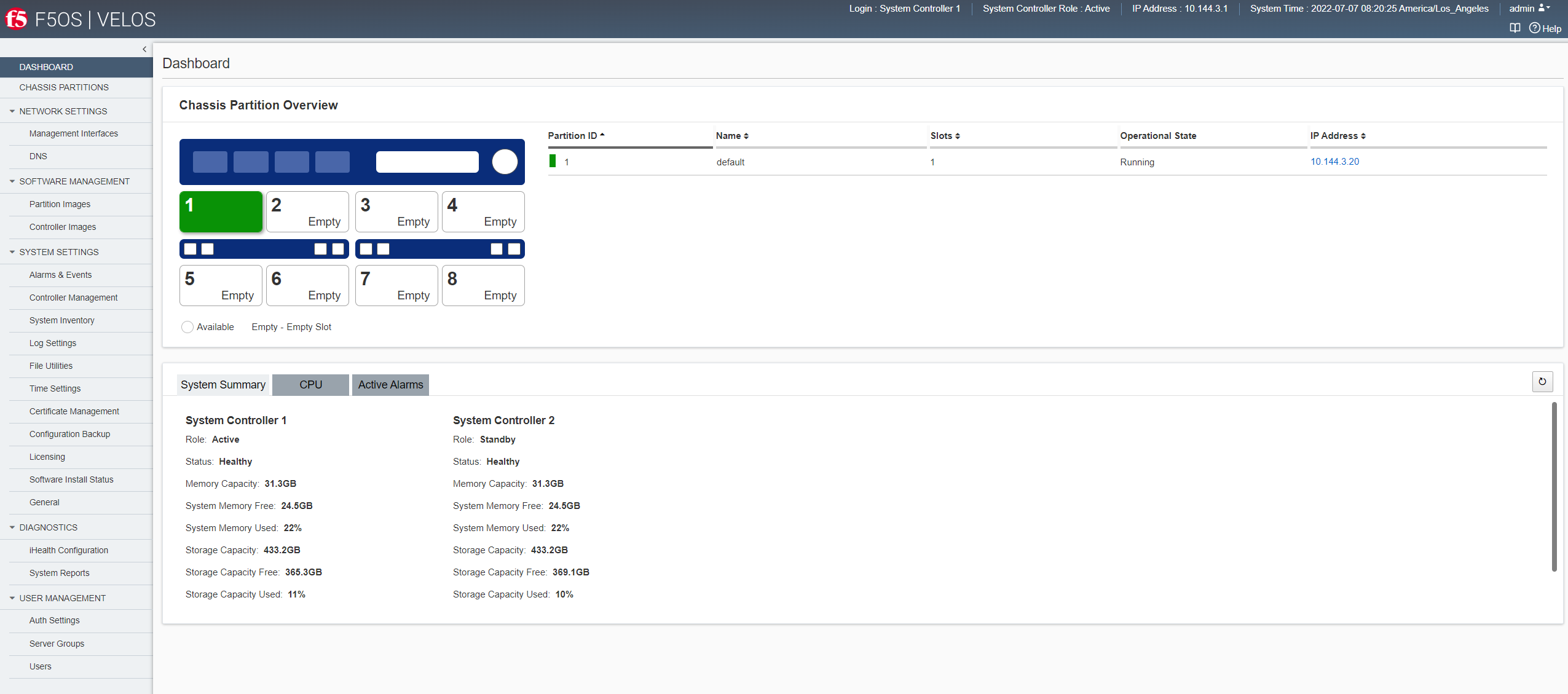
From a web browser, log in to the system controller using the floating IP address and the admin account.
The System Controller Dashboard displays and shows a graphical view of the chassis initially preconfigured with one default chassis partition. The slots for all blades are automatically assigned as members of that partition.
-
To get contextual online Help, click the button in the upper right.
Online Help for that particular screen displays.
-
To get an idea of the available menu items on the left, click on them.
Different sections in the menu let you manage chassis partitions, networking, system settings, and user authentication and accounts.
When you are done exploring the webUI, continue with initial configuration tasks.
If you want to change the internal IP address ranges, do that next. See the “Internal Chassis Networking” section of the VELOS System: Administration and Configuration guide on Support.f5.com.
You can license the system automatically from the webUI, as long as the system has internet access.
-
Log in to the VELOS system controller webUI using an account with admin access.
-
On the left, click SYSTEM SETTINGS > Licensing.
-
For the Base Registration Key field, the registration key is auto-populated.
You can choose to overwrite this field with a new registration key.
-
For the Add-On Keys field, the associated add-on keys are auto-populated.
You can click + or x to add or remove additional add-on keys.
Note: To add add-on keys to a licensed system, enter the keys in the Add-On Keys field and click Reactivate.
-
For the Activation Method, select Automatic.
-
Click Activate.
The End User License Agreement (EULA) displays.
-
Click Agree to accept the EULA, .
The system is now licensed. If a base registration key or add-on key fails to activate, try re-activating the license or contact support.f5.com.
After you have licensed the system, you can use the system controller webUI to configure the default chassis partition, which comes preconfigured on the system with the software already installed on it. The slots for all blades are automatically assigned as members of the default chassis partition, and you can use the default chassis partition to get started.
Note: The default chassis partition cannot be renamed, so if you plan to use more than one chassis partition, you might want to create new partitions with names that are appropriate for your environment. To do this, you must first edit the default chassis partition and remove any slots that you want to add to other partitions. Once a slot is removed from the default chassis partition, an option to create new chassis partitions is enabled. Slots that are not currently assigned to an existing chassis partition may be added to a new chassis partition.
-
Log in to the VELOS system controller webUI using an account with admin access.
-
On the left, click CHASSIS PARTITIONS.
The Chassis Partitions screen displays where you can see a graphical view of the VELOS chassis and see that the default chassis partition is already set up with all slots associated with it.
-
Click the check box next to the default chassis partition.
-
Click Edit.
-
To configure IPv4 addresses, in the IPv4 section:
-
For IP Address, type the IP address of the chassis partition.
-
For Prefix Length, enter a number from 1-32 for the length of the prefix.
-
For Gateway, type the IP address of the gateway.
-
-
To configure IPv6 addresses, in the IPv6 address section:
-
For IP Address, type the IP address of the chassis partition.
-
For Prefix Length, enter a number from 1-32 for the length of the prefix.
-
For Gateway, type the IP address of the gateway.
-
-
For Partition Image, select the software to use for the chassis partition:
Note: If you don’t select a chassis partition image, the chassis partition state will be Disabled, and you will get an error message.
-
Click Bundled to install the entire operating system for the chassis partition.
-
For ISO Image, select a software image to run on the chassis partition.
-
-
Click Save.
The changes that you made to the default chassis partition are saved and the chassis partition is set to Enabled.
Note: If the chassis partition does not change automatically to the Enabled state, you can manually select Enabled from the Enabled/Disabled list.
Note: It might take a few minutes for the Operational State to update to say Running.
When the Operational State is Running, you can log into the default chassis partition using its management IP address to access the chassis partition webUI and create any required VLANs.
You can use the chassis partition webUI to create VLANs. You can also associate physical interfaces or LAGs with VLANs. You can then add those VLANs to physical interfaces of Link Aggregation Groups (LAGs) within the chassis partition.You need to create VLANs and associate them to an interface or LAG before you can deploy a tenant.
-
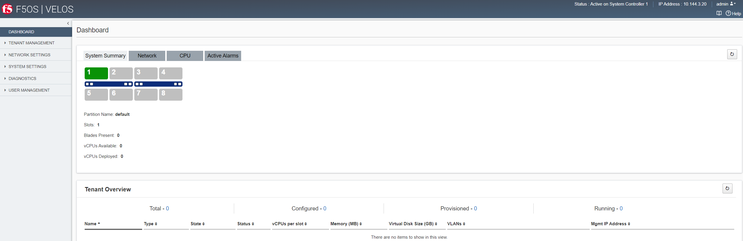
From a web browser, log in to the chassis partition using the IP address that you configured and the admin account.
The Chassis Partition Dashboard displays and shows a graphical system summary view.
-
On the left, click NETWORK SETTINGS > VLANs.
The screen shows VLANs that are configured for that chassis partition.
-
Click Add.
-
In the VLAN ID, enter a number between 1-4094 for the VLAN.
The VLAN ID identifies the traffic from hosts in the associated VLAN for an associated interface or LAG.
-
In the Name field, enter a name for the VLAN.
-
Click Save & Close.
A VLAN is created and displayed in the VLAN list. You can create additional VLANs, as required. You can use the VLANs when configuring interfaces and creating LAGs.
You can create a link aggregation group (LAG) or edit the properties of an existing LAG from the chassis partition webUI.
-
Log in to the VELOS chassis partition webUI using an account with admin access.
-
On the left, click NETWORK SETTINGS > LAGs.
The screen shows LAGs that are configured.
-
Click Add.
-
For Name, enter a name for the LAG.
-
For LAG Type, select one of these options:
Option Description STATIC Manually configure the links. The link state of LAG members is not dynamically updated. This is the default value for LAGs. LACP Automatically bundle links. -
If you select LACP, configure these additional settings:
|
Option |
Description |
|---|---|
|
LACP Interval |
Specify an interval at which interfaces send LACP packets. Select FAST (transmit packets every second) or SLOW (transmit packets every 30 seconds). |
|
LACP Mode |
Specify the negotiation state for LACP. Select ACTIVE (in an active negotiating state) or PASSIVE (do not initiate negotiation until peer contacts first). |
-
For Configured Members, select one or more interfaces (not members of another LAG) to assign to the LAG.
Note: Only interfaces that are configured with the same speeds can be members of the LAG. The interfaces cannot be associated with VLANs.
You can add up to 32 members to a LAG.
-
For Native VLAN, select the VLAN ID to use for untagged frames received on a trunk interface.
-
For Trunk VLANs, select one or more VLAN IDs, if available, and not a member of another LAG.
Note: A trunk VLAN or a native VLAN is required to pass traffic. If you do not select either a native VLAN or a trunk VLAN, the port will not carry any traffic.
-
Click Save & Close.
The LAG is created and shown in the list. You can edit LAG properties by clicking the LAG name. You can add up to 256 LAGs per partition. You can now deploy a tenant using the same chassis partition webUI.
Before you get started, decide to which slot or slots you want to deploy the tenant. If the tenant spans more than one blade, it will require additional IP addresses. You must also have created one or more VLANs in the chassis partition and assigned them to physical interfaces or LAGs before deploying the tenant. You might also choose to download the desired F5OS BIG-IP or BIG-IP Next tenant image from downloads.f5.com first, and then upload it to the chassis partition before deploying any tenant.
Note: It is recommended that you configure DNS and NTP configured at the VELOS system controller layer. If you are deploying a BIG-IP Next tenant, this is required.
You can deploy a BIG-IP or BIG-IP Next tenant from within the chassis partition. For information on downloading a tenant file, see VELOS Systems: Software Installation and Upgrade on my.f5.com.
-
Log in to the VELOS chassis partition webUI using an account with admin access.
-
On the left, click TENANT MANAGEMENT > Tenant Deployments.
The Tenant Deployment screen displays showing the existing tenant deployments and associated details.
-
To add a tenant deployment, click Add.
The Add Tenant Deployment screen displays.
-
For Name, enter a name for the tenant deployment (up to 49 characters).
Note: The first character in the name cannot be a number. After that, only lowercase alphanumeric characters and hyphens are allowed.
-
For Type, select the tenant type: BIG-IP or BIG-IP Next.
If you select BIG-IP Next, the Deployment File field displays. Select the deployment file.
-
For Image, select a software image.
Note: If no tenant software images are listed, you must import one onto the system. To do this, go to TENANT MANAGEMENT > Tenant Images.
-
For Allowed Slots, first select the appropriate option:
- Partition Member Slots lists only slots that the chassis partition includes.
- Any Slots lists any slot on the chassis even if not associated with the chassis partition, and even if no blade is installed in that slot. You have the option of selecting slots 1-8 whether or not they are associated with the chassis partition. This allows you to preconfigure tenant deployments before the hardware is installed and before the chassis partition is configured to include it. Then, select the slots (or blades) that you want the tenant to span from the list.
-
For IP Address, enter the IPv4 address, IPv6 address, or Fully Qualified Domain Name (FQDN) for the tenant.
-
For Prefix Length, enter a number for the length of the prefix.
The maximum prefix length is 32 for IPv4 and 128 for IPv6.
-
For Gateway, enter the IPv4 address or IPv6 address of the gateway.
-
For VLANs, select the VLANs you want this tenant to have access to.
-
For Resource Provisioning, select Recommended.
This specifies recommended values for vCPUs and memory for the tenant.
-
For vCPUs Per Slot, select the desired number of vCPUs for this tenant, up to the maximum number of vCPUs allowed on your system. When deploying a BIG-IP Next tenant, select 10, 12, or 22.
When you create multiple tenants, each gets dedicated vCPU resources.
-
For Memory Per Slot, accept the default values.
-
For Virtual Disk Size, select the disk size in gigabytes.
-
For State, choose Deployed.
This changes the tenant to the Deployed state. The tenant is set up, resources are allocated to the tenant, the image is moved onto the system, the software is installed, and after those tasks are complete, the tenant is fully deployed and running. If you choose this option, it takes a few minutes to complete the deployment and bring up the system.
-
For Crypto/Compression Acceleration, select Enabled.
When this option is enabled, the tenant receives crypto devices proportional to the number of vCPU cores. Crypto processing and compression are off-loaded to the hardware. This option is not supported on BIG-IP Next tenants.
-
For Appliance Mode, accept the default value (Disabled).
-
Click Save & Close.
The tenant is now configured and in the Deployed state. When the status says Running, the tenant administrator can use the management IP address to connect to the tenant’s web-based user interface or connect using SSH to the CLI, and then continue configuring the tenant system.
Note: If the Status is Pending instead of Running, this might mean that there are not enough resources (vCPUs, memory, or other resources) for the tenant to be deployed. See the Tenant Details screen in the webUI for more information about the specific tenant.