Applies To:
Show Versions
BIG-IP AAM
- 11.5.10, 11.5.9, 11.5.8, 11.5.7, 11.5.6, 11.5.5, 11.5.4, 11.5.3, 11.5.2, 11.5.1
Overview: Configuring a one-arm deployment using WCCPv2
In certain cases, it is not advantageous or even possible to deploy the BIG-IP system inline. For example, in the case of a collapsed backbone where the WAN router and the LAN switch are in one physical device, you might not be able to deploy the BIG-IP system inline.
If you choose not to deploy the BIG-IP system inline, you can use a one-arm deployment. In a one-arm deployment, the BIG-IP system has a single (hence, one-arm) connection to the WAN router or LAN switch. The WAN router (or switch) redirects all relevant traffic to the BIG-IP system. In this configuration, the WAN router typically uses Web Cache Communication Protocol version 2 (WCCPv2) to redirect traffic to the BIG-IP system.
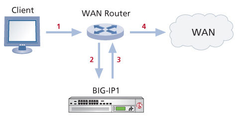 Network topology for a one-arm connection
The traffic flow sequence in this illustration is as follows:
- The client initiates a session.
- A WAN router redirects traffic to the BIG-IP system.
- The BIG-IP1 processes traffic and sends it back to the WAN router.
- The WAN router forwards traffic across the WAN.
About WCCPv2 redirection on the BIG-IP system
TMOS includes support for Web Cache Communication Protocol version 2 (WCCPv2). WCCPv2 is a content-routing protocol developed by Cisco Systems. It provides a mechanism to redirect traffic flows in real time. The primary purpose of the interaction between WCCPv2-enabled routers and a BIG-IP system is to establish and maintain the transparent redirection of selected types of traffic flowing through those routers.
To use WCCPv2, you must enable WCCPv2 on one or more routers connected to the BIG-IP system, and configure a service group on the BIG-IP system that includes the router information. The BIG-IP system then receives all the network traffic from each router in the associated service group, and determines both the traffic to optimize and the traffic to which to apply a service.
In configuring WCCPv2 on a network, you define a service group on the BIG-IP system, which is a collection of WCCPv2 services configured on the BIG-IP system. A WCCPv2 service in this context is a set of redirection criteria and processing instructions that the BIG-IP system applies to any traffic that a router in the service group redirects to the BIG-IP system. Each service matches a service identifier on the router.
The following illustration shows a one-arm configuration on one side of the WAN and an inline (bridge) configuration on the other side.
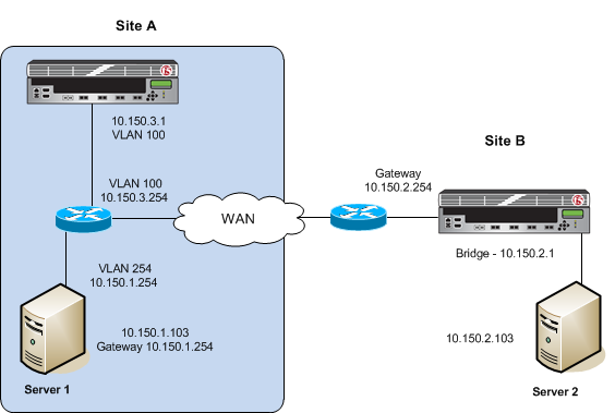 Example of a one-arm configuration
Before you begin configuring an iSession connection
Before you configure an iSession connection on the BIG-IP system, make sure that you have completed the following general prerequisites.
- You must have an existing routed IP network between the two locations where the BIG-IP devices will be installed.
- One BIG-IP system is located on each side of the WAN network you are using.
- The BIG-IP hardware is installed with an initial network configuration applied.
- F5 recommends that both units be running the same BIG-IP software version.
- The Application Acceleration Manager license is enabled.
- Application Acceleration Manager (AAM) is provisioned at the level Nominal.
- The management IP address is configured on the BIG-IP system.
- You must have administrative access to both the Web management and SSH command line interfaces on the BIG-IP system.
- If there are firewalls, you must have TCP port 443 open in both directions. Optionally, you can allow TCP port 22 for SSH access to the command line interface for configuration verification, but not for actual BIG-IP iSession traffic. After you configure the BIG-IP system, you can perform this verification from the Configuration utility ().
Task summary
To use WCCPv2 for traffic redirection, you configure a service group on the BIG-IP system that includes at least one service. You also configure this service on the WCCPv2-enabled router connected to the BIG-IP system.
For optimization, you also need to configure the BIG-IP system on the other side of the WAN to complete the connection. The BIG-IP system on the other side of the WAN can be set up in either a one-arm or inline configuration.
Prerequisites
Before you begin configuring WCCPv2 for traffic redirection, ensure that you have performed the following actions on the other devices in your network.
- The interface and associated VLAN have been configured on the router or switch. For instructions, refer to the Cisco documentation for your device.
- IP addresses have been assigned on the Cisco router or switch interface. Note the router identification address, which you will use when configuring WCCPv2 on the BIG-IP system.
Task list
Creating a VLAN for a one-arm deployment
Creating a self IP address for a one-arm deployment
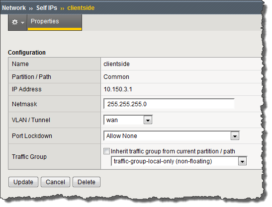 Example of the Properties screen for the self IP address you created
Defining a route
Configuring WCCPv2
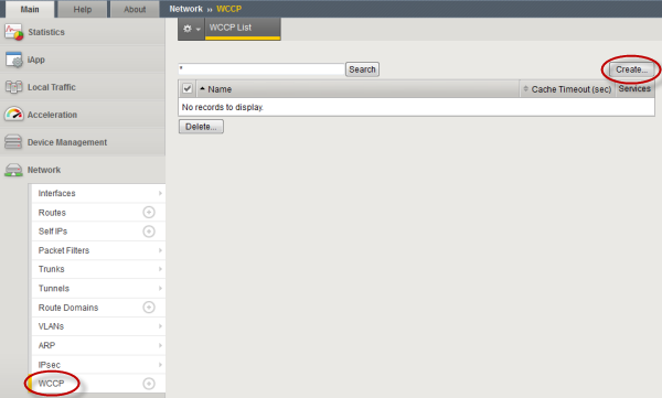 Example showing browser interface for configuring WCCP
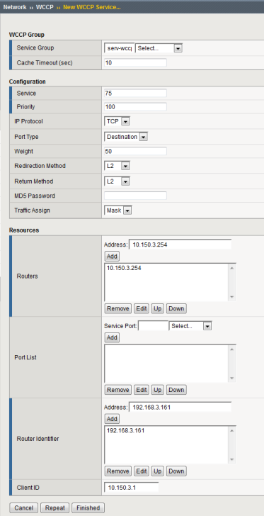 Example of completed configuration screen
Verifying connectivity
Verifying WCCPv2 configuration for one-arm deployment
Creating an iSession connection
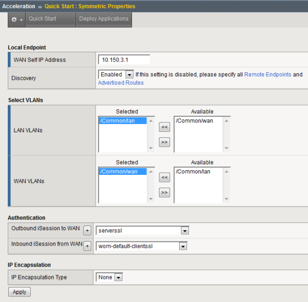 Example of completed Quick Start screen


