Applies To:
Show Versions
BIG-IP AAM
- 11.5.10, 11.5.9, 11.5.8, 11.5.7, 11.5.6, 11.5.5, 11.5.4, 11.5.3, 11.5.2, 11.5.1
Overview: Configuring the BIG-IP system in bridge mode
A bridge deployment is one method of deploying a BIG-IP system directly in the path of traffic, such as between a WAN router and LAN switch. In bridge mode, the BIG-IP system is transparent on the network, and the system optimizes traffic using a single bridge self IP address. This configuration allows the BIG-IP system to bridge the LAN and WAN subnets, and requires no changes to the router configuration.
Illustration of a bridge deployment
This illustration shows a pair of BIG-IP systems in a bridge deployment (Site B) on one side of the WAN, and a one-arm deployment on the other side.
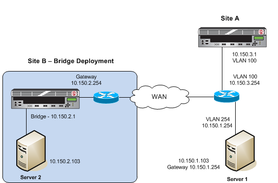 Example of a bridge deployment
Before you begin configuring an iSession connection
Before you configure an iSession connection on the BIG-IP system, make sure that you have completed the following general prerequisites.
- You must have an existing routed IP network between the two locations where the BIG-IP devices will be installed.
- One BIG-IP system is located on each side of the WAN network you are using.
- The BIG-IP hardware is installed with an initial network configuration applied.
- F5 recommends that both units be running the same BIG-IP software version.
- The Application Acceleration Manager license is enabled.
- Application Acceleration Manager (AAM) is provisioned at the level Nominal.
- The management IP address is configured on the BIG-IP system.
- You must have administrative access to both the Web management and SSH command line interfaces on the BIG-IP system.
- If there are firewalls, you must have TCP port 443 open in both directions. Optionally, you can allow TCP port 22 for SSH access to the command line interface for configuration verification, but not for actual BIG-IP iSession traffic. After you configure the BIG-IP system, you can perform this verification from the Configuration utility ().
Task summary
If you are configuring a BIG-IP system in bridge mode, you configure two VLANs and a VLAN group, and then associate a self IP address with the VLAN group.
Task list
Creating a VLAN group
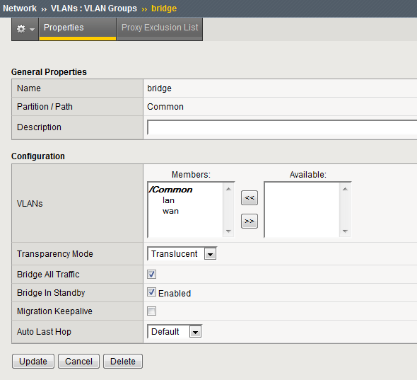 Example of VLAN group for bridge deployment
Creating a self IP address for a VLAN group
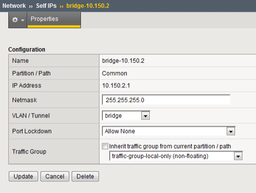 Example of self IP address assigned to VLAN group
Defining a route
Checking connectivity
- Ping the gateway using the command-line access to the BIG-IP system.
- Ping end-to-end across the WAN. In the example shown, this is between Server 1 and Server 2.
- Initiate a TCP file transfer between Server 1 and Server 2.
Setting up an iSession connection using the Quick Start screen
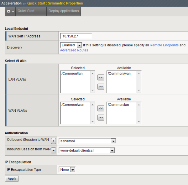 Example of completed Quick Start screen
Validating iSession configuration
Implementation result
After you complete the tasks in this implementation, the BIG-IP system is configured in a bridge deployment. For symmetric optimization using an iSession connection, you must also configure the BIG-IP system on the other side of the WAN. The other BIG-IP deployment can be in bridge, routed, or one-arm mode.


