Applies To:
Show Versions
BIG-IP DNS
- 13.1.5, 13.1.4, 13.1.3, 13.1.1, 13.1.0
How do I configure BIG-IP DNS to load balance DNS requests to specific resources?
You can configure BIG-IP® DNS to load balance DNS requests to a resource based on the physical proximity of the resource to the client making the request. You can also configure BIG-IP DNS to deliver region-specific content, such as news and weather, to a client making a request from a specific location.
You can accomplish this by configuring BIG-IP DNS to perform Topology load balancing.
About Topology load balancing
Topology load balancing distributes DNS name resolution requests based on the proximity of the client to the data center housing the resource that responds to the request. When Topology load balancing is enabled, the BIG-IP® system uses topology records to make load balancing decisions.
Understanding topology records
A topology record is a set of characteristics that maps the origin of a DNS name resolution request to a destination. Each topology record contains the following elements:
- A request source statement that specifies the origin LDNS of a DNS request.
- A destination statement that specifies the pool or pool member to which the weight of the topology record will be assigned.
- A weight that the BIG-IP® system assigns to a pool or a pool member
during the load balancing process. Note: In tmsh, the weight parameter is called score.
Understanding user-defined regions
A region is a customized collection of topologies that defines a specific geographical location that has meaning for your network. For example, you can create two custom regions named Region_east and Region_west. Region_east includes the states on the east coast of the United States. Region_west includes the states on the west coast of the United States Then, you can use those custom regions as the Request Source or Destination of a topology record you create.
This table describes how the use of topology regions improves the load-balancing performance of the BIG-IP® system.
| Faster load balancing configuration | Slower load balancing configuration |
|---|---|
| 2 data centers | 2 data centers |
| 1000 pool members in each data center | 1000 pool members in each data center |
| 2 regions with 5000 CIDR entries each | |
| 2 topology records: | 10,000 topology records: |
| 1 entry routes all requests from Region_east to data center1 | 5000 CIDR topology records route requests to data center1 |
| 1 entry routes all requests from Region_west to data center2 | 5000 CIDR topology records route requests to data center2 |
Creating a region for Topology load balancing
Understanding how the BIG-IP system prioritizes topology records
When Topology load balancing is configured, the order of the topology records is vital and affects how the BIG-IP® system scores the pools or pool members to which it load balances DNS name resolution requests. By default, the BIG-IP system prioritizes topology records using Longest Match sorting. As a result, topology records are automatically sorted based on a specific criteria each time the BIG-IP system configuration loads. Alternatively, you can disable Longest Match sorting and customize the order of the topology records in the list.
Understanding Longest Match topology record sorting
When Longest Match is enabled, the BIG-IP® system sorts the topology records by the LDNS request source statement, the destination statement, and the weight of the record.
The system first sorts the topology records by the type of LDNS request source statement using this order from highest to lowest:
- IP subnet in CIDR format (the system places the most specific IP subnet at the top of the list; for example, 10.15.1.1/32, 10.15.1.0/24, 10.15.0.0/16, 10.0.0.0/8)
- Region
- ISP
- State
- Country
- Continent
- LDNS Request Source negation (record that excludes an LDNS)
- Wildcard record (the system sorts the wildcard record to the bottom of the list, because this record is the least specific)
If the type of LDNS request source statement is the same in multiple topology records, the BIG-IP system then sorts these records by the type of destination statement using this order from highest to lowest:
- IP subnet in CIDR format (the system places the most specific IP subnet at the top of the list; for example, 10.15.1.1/32, 10.15.1.0/24, 10.15.0.0/16, 10.0.0.0/8)
- Data center
- Pool
- Region (customized collection of criteria)
- ISP
- State
- Country
- Continent
- Destination negation (record that excludes a destination)
- Wildcard record (the system sorts the wildcard record to the bottom of the list, because this record is the least specific)
If the type of LDNS request source statement is the same in multiple topology records and the type of destination statement is the same in those records, the system then uses the value of the weight from highest to lowest to sort the records.
The example shows a list of topology records sorted automatically using Longest Match. Note that the fourth and fifth records have the same LDNS subnet and the destinations are both of type State. Therefore, the weight determines the position in the list; thus, the record with the highest weight is first.
- ldns: subnet 192.168.69.133/32 destination: subnet 10.15.1.1/32 weight: 500
- ldns: subnet 192.168.69.133/32 destination: datacenter /Common/NorthAmerica weight: 400
- ldns: subnet 192.168.69.0/24 destination: pool /Common/NorthAmerica weight 300
- ldns: subnet 192.168.0.0/16 destination: state NY weight 200
- ldns: subnet 192.168.0.0/16 destination: state WA weight 100
Customizing the sort order of topology records
- On the Main tab, click .
- Click the Change Order button.
- Clear the Longest Match check box.
-
To change the order of the records in the Topology Record List, do the
following:
- From the list, select a topology record.
- Click the Up or Down button to move the record to the preferred position in the list.
- Click Update.
Configuring Longest Match
- On the Main tab, click .
- Click the Change Order button.
- Select the Longest Match check box.
- Click Update.
Creating a topology record
Deleting a topology record
About Topology load balancing for a wide IP
When you use the topology load balancing method at a wide IP level with topology records that have a Data Center destination, the topology records have no effect. (This is because load balancing at a wide IP level selects between GTM pools, and GTM pools do not have a data center associated with them.) Topology records that have a Data Center destination have an effect only when using the topology load balancing method at the pool level.
Example configuration: Topology load balancing for a wide IP
This example illustrates how DNS name resolution requests are load balanced when a wide IP is configured for Topology load balancing. An administrator configures the wide IP www.siterequest.net for Topology load balancing. The wide IP contains three pools: Pool1 and Pool3 are located in the North America data center; Pool2 is located in the South America data center. Next, the administrator creates topology records, as shown in this figure, and ensures that Longest Match is enabled on the BIG-IP® system.
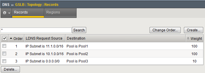
Topology records for a wide IP configured for Topology load balancing
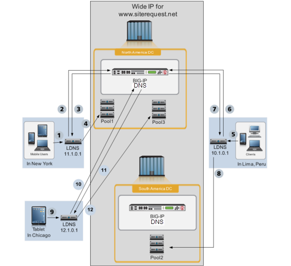
BIG-IP system load balancing DNS requests using a wide IP configured for Topology load balancing
- A client in New York makes a DNS request.
- LDNS 11.1.0.1 queries the BIG-IP system in the North America data center.
- The BIG-IP system directs the LDNS to Pool1. To determine this answer, for each pool, one at a time, the BIG-IP system iterates through the list of two topology records to find a match. Pool1 matches the first topology record in the list, because both the LDNS request source (11.1.0.1) and the Destination (Pool1) of the DNS request match the first topology record; therefore, the BIG-IP system assigns a score of 100 to Pool1. For Pool2, there is no matching topology record that contains both the LDNS request source (11.1.0.1) and the Destination (Pool2); therefore, the BIG-IP system assigns a score of zero to Pool2. Pool3, matches the third topology record in the list, because both the LDNS request source (11.1.0.1) and the Destination (Pool3) of the DNS request match the third topology record; therefore, the BIG-IP system assigns a score of 10 to Pool3. The BIG-IP system directs the LDNS to send the request to the pool with the highest score.
- The LDNS sends the DNS request to Pool1 in the North America data center. How the system distributes the DNS requests to the members of Pool1 is not depicted in this illustration, but is based on the load balancing method configured for Pool1.
- A client in Lima makes a DNS request.
- LDNS 10.1.0.1 queries the BIG-IP system in the North America data center.
- The BIG-IP system directs the LDNS to Pool2. To determine this answer, for each pool, one at a time, the BIG-IP system iterates through the list of two topology records to find a match. For Pool1, there is not a matching topology record that contains both the LDNS request source (10.1.0.1) and the Destination (Pool1); therefore, the BIG-IP system assigns a score of zero to Pool1. Pool2 matches the second topology record in the list, because both the LDNS request source (10.1.0.1) and the Destination (Pool2) of the DNS request match the second topology record; therefore, the BIG-IP system assigns a score of 100 to Pool2. Pool3, matches the third topology record in the list, because both the LDNS request source (10.1.0.1) and the Destination (Pool3) of the DNS request match the third topology record; therefore, the BIG-IP system assigns a score of 10 to Pool3. The BIG-IP system directs the LDNS to send the request to the pool with the highest score.
- The LDNS sends the DNS request to Pool2 in the South America data center. How the system distributes the DNS requests to the members of Pool2 is not shown in this illustration, but is based on the load balancing method configured for Pool2.
- A client in Chicago makes a DNS request.
- LDNS 12.1.0.1 queries the BIG-IP system in the North America data center.
- The BIG-IP system directs the LDNS to Pool3. To determine this answer, for each pool, one at a time, the BIG-IP system iterates through the list of two topology records to find a match. For Pool1, there is not a matching topology record that contains both the LDNS request source (12.1.0.1) and the Destination (Pool1); therefore, the BIG-IP system assigns a score of zero to Pool1. For Pool2, there is not a matching topology record that contains both the LDNS request source (12.1.0.1) and the Destination (Pool1); therefore, the BIG-IP system assigns a score of zero to Pool2. Pool3, matches the third topology record in the list, because both the LDNS request source (12.1.0.1) and the Destination (Pool3) of the DNS request match the third topology record; therefore, the BIG-IP system assigns a score of 10 to Pool3. The BIG-IP system directs the LDNS to send the request to the pool with the highest score.
- The LDNS sends the DNS request to Pool3 in the North America data center. How the system distributes the DNS requests to the members of Pool3 is not depicted in this illustration, but is based on the load balancing method configured for Pool3.
Configuring a wide IP for Topology load balancing
- At least two pools are associated with the wide IP that you are configuring for Topology load balancing.
- Topology records that define how you want the BIG-IP® system to load balance DNS name resolution requests are configured.
About Topology load balancing for a pool
When you configure a pool for Topology load balancing, you can route DNS requests to the data center that is closest to the client making the request. With this configuration, the BIG-IP® system load balances DNS name resolution requests to the members of the pool.
Example configuration: Topology load balancing for a pool
This example illustrates how DNS name resolution requests are load balanced when a pool is configured for Topology load balancing. An administrator configures pools in two different data centers: the North America data center (North America DC) and the South America data center (South America DC) for Topology load balancing. A server that contains the pool members 10.10.10.1 - 10.10.10.3 resides in the North America DC. The server that contains the pool members 11.10.10.1 - 11.10.10.3 resides in the South America DC. Next, the administrator creates topology records, as shown in the following figure, to load balance DNS requests to members of the pools, and ensures that Longest Match is enabled on the BIG-IP® system.
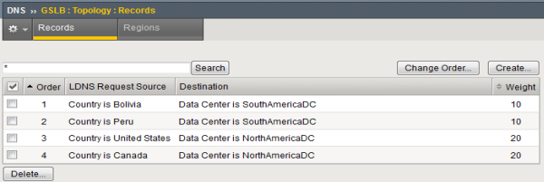
Topology records for a pool configured for Topology load balancing
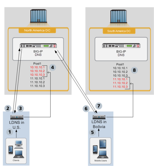
Pool configured for Topology load balancing
- A client in the U.S. makes a DNS request.
- An LDNS in the U.S. queries the BIG-IP system in the North America DC.
- The BIG-IP system directs the LDNS to a member of Pool1 in the North America DC. To determine this answer, for each pool member, one at a time, the BIG-IP system iterates through the list of topology records to find a match. Pool members 10.10.10.1 - 10.10.10.3 each match the third topology record in the list, because both the LDNS request source (U.S.) and the Destination (North America DC) of the DNS request match the third topology record; therefore, the BIG-IP system assigns a score of 20 to each of those pool members. For each of the pool members 11.10.10.1 - 11.10.10.3, there is no matching topology record that contains both the LDNS request source (U.S.) and the Destination (South America DC); therefore, the BIG-IP system assigns a score of zero to each of those pool members. The BIG-IP system directs the LDNS to send the request to the pool member with the highest score.
- The LDNS sends the DNS request to a pool member in the North America DC. Because all of the pool members in the North America DC have the same score, the system distributes the DNS requests to the pool members in a round robin fashion.
- A client in Bolivia makes a DNS request.
- An LDNS in Bolivia queries the BIG-IP system in the North America DC.
- The BIG-IP system directs the LDNS to a pool member in the South America DC. To determine this answer, for each pool member, one at a time, the BIG-IP system iterates through the list of topology records to find a match. For each of the pool members 10.10.10.1 - 10.10.10.3 there is no matching topology record that contains both the LDNS request source (Bolivia) and the Destination (North America DC); therefore, the BIG-IP system assigns a score of zero to each of those pool members. Pool members 11.10.10.1 - 11.10.10.3 each match the first topology record in the list, because both the LDNS request source (Bolivia) and the Destination (South America DC) of the DNS request match the first topology record; therefore, the BIG-IP system assigns a score of 10 to each of those pool members. The BIG-IP system directs the LDNS to send the request to the pool member with the highest score.
- The LDNS sends the DNS request to a pool member in the South America DC. Because all of the pool members in the South America DC have the same score, the system distributes the DNS requests to the pool members in a round robin fashion.
Configuring a pool for Topology load balancing
- The pool you are configuring for Topology load balancing contains at least two pool members.
- Topology records that define how you want the BIG-IP® system to load balance DNS name resolution requests are configured.
About Topology load balancing for both wide IPs and pools
You can configure a wide IP for Topology load balancing. You can also configure each pool in the wide IP for Topology load balancing. When you configure both a wide IP and the pools in the wide IP for Topology load balancing, the BIG-IP® system uses topology records to load balance DNS name resolution requests first to a pool in the wide IP, and then, to a member of the pool.
When configuring both the wide IP and the pools in the wide IP for Topology load balancing, it is important to set the Fallback load balancing method for each pool to None. If you do not, DNS can send a DNS request to a pool in the wide IP even when no pool members are available. In this case, the load balancing algorithm for the pool would then fall back to BIND (static DNS). When you set the Fallback load balancing method for each pool to None, if no members of a pool are available, BIG-IP DNS sends the DNS request to another pool in the wide IP.
About Topology load balancing for CNAME wide IPs and pools
For a CNAME query against a CNAME wide IP with a CNAME pool, you can use Topology load balancing at the wide IP level to make a pool selection, given that matching topology entries are configured to specify a CNAME pool on the wide IP. However, when using Topology load balancing at the pool level to make pool member selections, the BIG-IP® system relies on a metrics pull-up to get the topology scores needed to pick a pool member because the pool members are non-terminal.
If the pool members are terminal members (for example, on an A or AAAA type pool), then you can use them to match against the topology entries and get scores. But Topology load balancing cannot be used to get scores for non-terminal members without doing a metrics pull-up because there is no way to specify a wide IP or DNS name in a given topology entry. Therefore, for a CNAME query against a CNAME wide IP with a CNAME pool, you can use Topology load balancing to pick a pool at the wide IP level, but it will not be used (even if configured) at the pool level to pick a pool member because the BIG-IP system will not perform a metrics pull-up.
About IP geolocation data
The BIG-IP® system uses an IP geolocation database to determine the origin of DNS requests. The database included with the BIG-IP system provides geolocation data for IPv6 addresses at the continent and country levels. It also provides geolocation data for IPv4 addresses at the continent, country, state, ISP, and organization levels. The state-level data is worldwide, and thus includes designations in other countries that correspond to the U.S. state-level in the geolocation hierarchy, such as, provinces in Canada.
About topology records and IP geolocation data
The BIG-IP® system uses an IP geolocation database to determine the IP addresses that match the geographic names that you define in a topology record, such as continent and country.


