Applies To:
Show Versions
BIG-IP AAM
- 13.0.1, 13.0.0
BIG-IP APM
- 13.0.1, 13.0.0
BIG-IP LTM
- 13.0.1, 13.0.0
BIG-IP AFM
- 13.0.1, 13.0.0
BIG-IP ASM
- 13.0.1, 13.0.0
Overview: Configuring network virtualization tunnels
Large data centers and cloud service providers are benefiting from large scale network virtualization. Network Virtualization provides connectivity in cloud environments by overlaying Layer 2 segments over a Layer 3 infrastructure. The overlay network can be dynamically extended with multiple virtualized networks without affecting the Layer 3 infrastructure. This number of virtualized networks is typically much larger than the number of VLANS the infrastructure can support.
You can configure a BIG-IP® system to function as a gateway in a virtualized network, bridging the data center virtualized networks with the physical network (L2 gateway), or performing routing and higher L4-L7 functionality among virtual networks of different types (L3 gateway). Connecting these networks allows for expansion, and provides a mechanism to streamline the transition of data centers into a virtualized model, while maintaining connectivity.
This illustration shows the BIG-IP system as a network virtualization gateway.
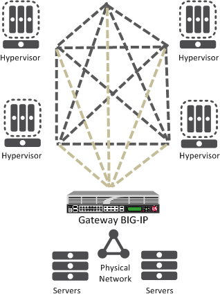
The BIG-IP system as a network virtualization gateway
In a virtualized network, the BIG-IP system needs to learn about other virtualization tunnel endpoints. Each hypervisor has a tunnel endpoint. The hypervisor needs to locate the virtual machines it manages, by maintaining a form of the L2 location records, typically, IP addresses and MAC addresses, virtual network identifiers, and virtual tunnel endpoints.
About network virtualization tunnels on the BIG-IP system
When you configure a BIG-IP® system as a network virtualization gateway, the system represents the connection as a tunnel, which provides a Layer 2 interface on the virtual network. You can use the tunnel interface in both Layer 2 and Layer 3 configurations. After you create the network virtualization tunnels, you can use the tunnels like you use VLANs on a BIG-IP system, such as for routing, assigning self IP addresses, and associating with virtual servers.
Creating a network virtualization tunnel
Virtualized network terminology
These terms are associated with virtualized networks.
- forwarding database (FDB)
- The FDB is the database that contains mappings between the MAC address of each virtual machine and the IP address of the hypervisor machine on which it resides.
- L2 gateway
- The Layer 2 gateway performs the bridge functionality between VLAN and virtual segments in a virtualized network.
- L3 gateway
- The Layer 3 gateway performs routing and higher L4-L7 functionality among virtualized network segments of different types.
- overlay network
- The overlay network is a virtual network of VMs built on top of a stable L2-L3 structure. The view from one VM to another is as if they were on the same switch, but, in fact, they could be far afield.
- tunnel endpoint
- A tunnel endpoint originates or terminates a tunnel. In a virtualized network environment, the tunnel IP addresses are part of the L2 underlay network. The same local IP address can be used for multiple tunnels.
- underlay network
- The underlay network is the L2 or L3 routed physical network, a mesh of tunnels.
- virtualized network
- A virtualized network is when you create a virtual L2 or L3 topology on top of a stable physical L2 or L3 network. Connectivity in the virtual topology is provided by tunneling Ethernet frames in IP over the physical network.
- VNI
- The Virtual Network Identifier (VNI) is also called the VXLAN segment ID. The system uses the VNI to identify the appropriate tunnel.
- VSID
- The Virtual Subnet Identifier (VSID) is a 24-bit identifier used in an NVGRE environment that represents a virtual L2 broadcast domain, enabling routes to be configured between virtual subnets.
- VTEP
- The VXLAN Tunnel Endpoint (VTEP) originates or terminates a VXLAN tunnel. The same local IP address can be used for multiple tunnels.
- VXLAN
- Virtual eXtended LAN (VXLAN) is a network virtualization scheme that overlays Layer 2 over Layer 3. VLXAN uses Layer 3 multicast to support the transmission of multicast and broadcast traffic in the virtual network, while decoupling the virtualized network from the physical infrastructure.
- VXLAN gateway
- A VXLAN gateway bridges traffic between VXLAN and non-VXLAN environments. The BIG-IP® system uses a VXLAN gateway to bridge a traditional VLAN and a VXLAN network, by becoming a network virtualization endpoint.
- VXLAN header
- In addition to the UDP header, encapsulated packets include a VXLAN header, which carries a 24-bit VNI to uniquely identify Layer 2 segments within the overlay.
- VXLAN segment
- A VXLAN segment is a Layer 2 overlay network over which VMs communicate. Only VMs within the same VXLAN segment can communicate with each other.
Centralized vs. decentralized models of network virtualization
Using the BIG-IP® system as a network virtualization gateway, you can set up virtualized network segments using either a centralized or decentralized model.
Centralized model
In a centralized model, a network orchestrator or controller manages the virtualized network segments. The orchestrator has full view of VTEPs, L2, and L3 information in the overlay, and is responsible for pushing this information to hypervisors and gateways. Microsoft Hyper-V and VMware NSX environments use this model.
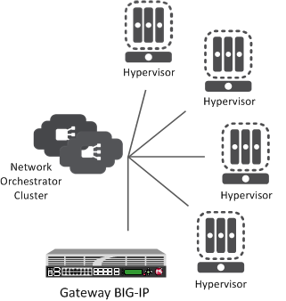
Centralized model of network virtualization
Decentralized model
A decentralized model of network virtualization does not require a network orchestrator or controller. In this model, the router learns the tunnel endpoint and MAC address locations by flooding broadcast, multicast, and unknown destination frames over IP multicast. VMware vSphere 5.1 environments use this model.
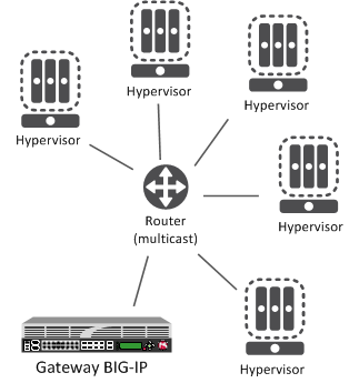
Decentralized model of network virtualization
About network virtualization tunnel types
The BIG-IP® system supports multiple network virtualization tunnel types. You can even combine virtualized network segments based on different tunnel types. This table offers a quick comparison of the tunnel types.
| VXLAN (Multicast) | VXLAN (Unicast) | NVGRE | Transparent Ethernet Bridging |
|---|---|---|---|
| Decentralized | Centralized | Centralized | Centralized |
| VMware vSphere 5.1 | VMware NSX | Microsoft SCVMM/Hyper-V | OpenStack |
| VXLAN UDP Encapsulation | VXLAN UDP Encapsulation | GRE-based Encapsulation | GRE-based Encapsulation |
| 24-bit ID | 24-bit ID | 24-bit ID | 32-bit ID |
| Endpoints discovered dynamically | Endpoints statically configured | Endpoints statically configured | Endpoints statically configured |
| Floods unknown and broadcast frames using IP multicast. | Can flood using unicast replication. | Does not flood (completely static). | Floods using unicast replication. |
About statically configured network virtualization tunnels
For the centralized model, you can use VXLAN (Unicast), NVGRE, or Transparent Ethernet Bridging, depending on the cloud environment. Using an agent or plug-in, or the tmsh command-line utility, you can statically configure the FDB and ARP forwarding table entries. Using the tmsh command-line utility or browser interface, you can create the network virtualization tunnels, which are managed by the network controller.
Considerations for statically configured network virtualization tunnels
As you configure a BIG-IP® system to be an L2 or L3 gateway for statically configured network virtualization tunnels, keep these considerations in mind.
- The BIG-IP system must be licensed for SDN Services.
- If you have over 2000 tunnels, set the Management (MGMT) setting on the Resource Provisioning screen is to Large ().
Examples for manually populating L2 location records
Using the tmsh command-line utility, you can add static FDB records and ARP entries for each virtual tunnel endpoint.
- Add static FDB (forwarding database) entries to associate MAC addresses with specified tunnel
endpoints. For example, the following command creates an FDB entry that associates the MAC
address 00:01:02:03:04:05 with the tunnel endpoint
10.1.1.1 of the tunnel vxlan0.
# tmsh modify net fdb tunnel vxlan0 records add { 00:01:02:03:04:05 { endpoint 10.1.1.1 } } - Delete a MAC address from an FDB entry.
# tmsh modify net fdb tunnel vxlan0 records delete { 00:01:02:03:04:05 } - Delete a static ARP.
# tmsh delete net arp 10.3.3.1
- Add an IP address to a MAC address in the ARP table.
# tmsh create net arp 10.3.3.1 { ip-address 10.3.3.1 mac-address 00:01:02:03:04:05 }
$ curl -u admin:f5site02 -H "Content-Type:=application/json" -k -X PUT
'https://172.30.69.69/mgmt/tm/net/fdb/tunnel/~Common~vxlan0-tunnel' -d
'{"kind":"tm:net:fdb:tunnel:tunnelstate","name":"vxlan0-tunnel","partition":"Common",
"fullPath":"/Common/vxlan0-tunnel","generation":1,
"selfLink":"https://localhost/mgmt/tm/net/fdb/tunnel/~Common~vxlan0-tunnel?
ver=11.5.0","records":[{"name":"00:01:02:03:04:05",
"endpoint":"10.1.1.2"}]}'  |python -m json.tool
{
    "fullPath": "/Common/vxlan0-tunnel",
    "generation": 1,
    "kind": "tm:net:fdb:tunnel:tunnelstate",
    "name": "vxlan0-tunnel",
    "partition": "Common",
    "records": [
        {
            "endpoint": "10.1.1.2",
            "name": "00:01:02:03:04:05"
        }
    ],
    "selfLink": "https://localhost/mgmt/tm/net/fdb/tunnel/~Common~vxlan0-tunnel?ver=11.5.0"
}
Commands for manually configuring FDB records of type "endpoints"
You can use the tunnel forwarding database (FDB) record type known as endpoints to configure a set of remote endpoints. The remote endpoints are used to send unknown destination, multicast, and broadcast frames. The MAC address for any endpoints record must be ff:ff:ff:ff:ff:ff.
The following commands show how to use the Traffic Management Shell (tmsh) to create and delete a record of endpoints.
Create a record of endpoints:
tmsh modify net fdb tunnel tunnel_name records add { ff:ff:ff:ff:ff:ff { endpoints add { IP_addresses } } }
Delete a record of endpoints:
tmsh modify net fdb tunnel tunnel_name records delete { ff:ff:ff:ff:ff:ff }
Sample NVGRE configuration using tmsh
This listing example illustrates the steps for creating a routing configuration that includes an NVGRE tunnel on the BIG-IP® system. F5 Networks provides an API for you to configure the F5 SCVMM Gateway Provider plug-in to build and manage NVGRE tunnels.
create net vlan wan {
    interfaces add { 1.1 }
    mtu 1550
}
create net self 10.1.1.1/24 {
    address 10.1.1.1/24
    vlan wan
}
create net tunnels gre nvgre {
    encapsulation nvgre
}
create net tunnels tunnel nvgre5000 {
    local-address 10.1.1.1
    remote-address any
    profile nvgre
    key 5000
}
create net vlan legacy5000 {
    interfaces add { 2.1 }
}
create net route-domain 5000 {
    id 5000
    vlans add { nvgre5000 legacy5000 }
}
create net self 10.3.3.1%5000/24 {
    address 10.3.3.1%5000/24
    vlan nvgre5000
}
create net self 10.4.4.1%5000/24 {
    address 10.4.4.1%5000/24
    vlan legacy5000
}
create net route 10.5.5.0%5000/24 {
    network 10.5.5.0%5000/24
    gw 10.3.3.2%5000
}
create net route 10.6.6.0%5000/24 {
    network 10.6.6.0%5000/24
    gw 10.3.3.3%5000
}
modify net fdb tunnel nvgre5000 {
    records add {
        00:FF:0A:03:03:02 { endpoint 10.1.2.1 }
        00:FF:0A:03:03:03 { endpoint 10.1.3.1 }
    }
}
create net arp 10.3.3.2%5000 {
    mac-address 00:FF:0A:03:03:02
}
create net arp 10.3.3.3%5000 {
    mac-address 00:FF:0A:03:03:03
}
Sample VXLAN unicast configuration using tmsh
This example listing illustrates the steps for creating a routing configuration that includes a VXLAN tunnel on the BIG-IP® system. This configuration adds the tunnel to a route domain. You can use the iControl/REST API to configure a network controller to build and manage VXLAN (unicast) tunnels.
create net vlan wan {
    interfaces add { 1.1 }
    mtu 1550
}
create net self 10.1.1./24 {
    address 10.1.1.1/24
    vlan wan
}
create net tunnels vxlan vxlan-static {
    flooding-type none
}
create net tunnels tunnel vxlan5000 {
    local-address 10.1.1.1
    remote-address any
    profile vxlan-static
    key 5000
}
create net vlan legacy5000 {
    interfaces add { 2.1 }
}
create net route-domain 5000 {
    id 5000
    vlans add {vxlan5000 legacy5000 }
}
create net self 10.3.3.1%5000/24 {
    address 10.3.3.1%5000/24
    vlan vxlan5000
}
create net self 10.4.4.1%5000/24 {
    address 10.4.4.1%5000/24
    vlan legacy5000
}
create net route 10.5.5.0%5000/24 {
    network 10.5.5.0%5000/24
    gw 10.3.3.2%5000
}
create net route 10.6.6.0%5000/24 {
    network 10.6.6.0%5000/24
    gw 10.3.3.3%5000
}
modify net fdb tunnel vxlan5000 {
    records add {
        00:FF:0A:03:03:02 { endpoint 10.1.2.1 }
        00:FF:0A:03:03:03 { endpoint 10.1.3.1 }
    }
}
create net arp 10.3.3.2%5000 {
    mac-address 00:FF:0A:03:03:02
}
create net arp 10.3.3.3%5000 {
    mac-address 00:FF:0A:03:03:03
}
Sample command for virtual server to listen on a VXLAN tunnel
# tmsh create ltm virtual http_virtual destination 10.3.3.15%5000:http ip-protocol tcp vlans add { vxlan5000 }
The
code in this example creates a virtual server http_virtual that listens
for traffic destined for the IP address 10.3.3.15 on the tunnel named
vxlan5000.Commands for viewing tunnel statistics
You can use the tmsh command-line utility to view tunnel statistics, listing either all the tunnels on the BIG-IP® system or statistics about a particular tunnel.
# tmsh show net tunnels tunnel
# tmsh show net fdb tunnel
About VXLAN multicast configuration
In a VMware vSphere 5.1 environment, you can configure VXLAN without knowing all the remote tunnel endpoints. The BIG-IP® system uses multicast flooding to learn unknown and broadcast frames. VXLAN can extend the virtual network across a set of hypervisors, providing L2 connectivity among the hosted virtual machines (VMs). Each hypervisor represents a VXLAN tunnel endpoint (VTEP). In this environment, you can configure a BIG-IP system as an L2 VXLAN gateway device to terminate the VXLAN tunnel and forward traffic to and from a physical network.
About bridging VLAN and VXLAN networks
You can configure Virtual eXtended LAN (VXLAN) on a BIG-IP® system to enable a physical VLAN to communicate with virtual machines (VMs) in a virtual network.
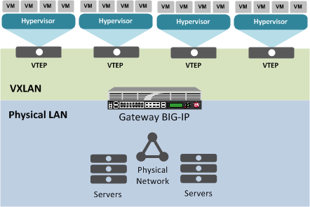
The VXLAN gateway
When you configure a BIG-IP system as an L2 VXLAN gateway, the BIG-IP system joins the configured multicast group, and can forward both unicast and multicast or broadcast frames on the virtual network. The BIG-IP system learns about MAC address and VTEP associations dynamically, thus avoiding unnecessary transmission of multicast traffic.
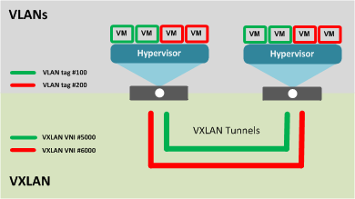
Multiple VXLAN tunnels
Considerations for configuring multicast VXLAN tunnels
As you configure VXLAN on a BIG-IP® system, keep these considerations in mind.
- If you configure the BIG-IP device as a bridge between physical VLANs and a VXLAN tunnel, the number of virtualized network segments in the overlay is limited to the maximum number of physical VLANs (4094). This limitation does not apply to Layer 3 configurations.
- You need to configure a separate tunnel for each VNI. The tunnels can have the same local and remote endpoint addresses.
- For the Layer 2 network, you must ensure a loop-free topology.
- Do not modify the configuration of a VXLAN tunnel after it is created. Instead, delete the existing tunnel and create a new one.
Task summary
Before you configure VXLAN, ensure that these conditions are met:
- The BIG-IP® system must be licensed for SDN Services.
- Network connectivity exists between the BIG-IP system and the hypervisors.
- If you have over 2000 tunnels, the Management (MGMT) setting on the Resource Provisioning screen is set to Large ().
Task list
Specifying a port number
When you enable the DAG tunnel feature on a VLAN, you must also configure a bigdb variable that specifies a port number so that associated tunnels can disaggregate based on the inner header of a packet.
Modifying a VLAN for disaggregation of VXLAN tunnel traffic
You perform this task when you want to use an existing VLAN with a VXLAN tunnel that disaggregates traffic based on the inner header of the packet (hardware-disaggregated or DAG tunnel).
Creating a multicast VXLAN tunnel
Creating a bridge between VXLAN and non-VXLAN networks
About configuring VXLAN tunnels on high availability BIG-IP device pairs
By default, the BIG-IP® system synchronizes all existing tunnel objects in its config sync operation. This operation requires that the local IP address of a tunnel be set to a floating self IP address. In a high availabilty (HA) configuration, any tunnel with a floating local IP address would be available only on the active device, which would prevent some features, such as health monitors, from using the tunnel on the standby device. To make a tunnel available on both the active and standby devices, you need to set the local IP address to a non-floating self IP address, which then requires that you exclude tunnels from the config sync operation. To disable the synchronization of tunnel objects, you can set a bigdb variable on both devices.
Disabling config sync for tunnels
About configuring VXLAN tunnels using OVSDB
The BIG-IP® system can create and delete VXLAN tunnels in an overlay segment using the Open vSwitch Database (OVSDB) management protocol. The system does this by communicating with a software-defined networking (SDN) controller that supports OVSDB.
For certain SDN controllers, you can use an orchestration plug-in to manage the creation and deletion of the VXLAN tunnels.
Once the plug-in creates the tunnel object, the OVSDB BIG-IP component creates and maintains any necessary L2 and L3 objects as directed by the SDN controller.
Setting up the OVSDB management component
About configuring VXLAN-GPE tunnels
You can configure a VXLAN Generic Protocol Extension (GPE) tunnel when you want to add fields to the VXLAN header. One of these fields is Next Protocol, with values for Ethernet, IPv4, IPv6, and Network Service Header (NSH).


