Applies To:
Show Versions
BIG-IP AAM
- 13.0.1, 13.0.0
BIG-IP APM
- 13.0.1, 13.0.0
BIG-IP LTM
- 13.0.1, 13.0.0
BIG-IP AFM
- 13.0.1, 13.0.0
BIG-IP ASM
- 13.0.1, 13.0.0
Overview: Configuring NVGRE tunnels for HA-paired devices
You can set up Network Virtualization using Generic Routing Encapsulation (NVGRE) tunnels on an HA pair of BIG-IP® devices. For NVGRE, you are creating a tunnel interface that can process packets to and from both floating and non-floating self IP addresses. The Local Address field specifies the floating tunnel IP address, and the Secondary Address field specifies the non-floating tunnel IP address. Monitor traffic uses the non-floating tunnel IP address, while forwarded traffic uses the floating tunnel IP address.
When you specify a secondary address, ConfigSync is disabled for the tunnel.
After you configure the NVGRE tunnel, two sets of NVGRE flows are created. The floating tunnel IP address is the source of one set of flows, and the non-floating tunnel IP address is the source of the other set. The NVGRE flows that originate from the floating tunnel IP address are available only on the active device.
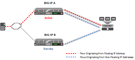
NVGRE tunnels configured for HA pair
After failover, the forwarded traffic flows through the tunnel associated with the floating IP address, which is now active on the other device. Monitor traffic continues to flow through the tunnels associated with the non-floating IP addresses.
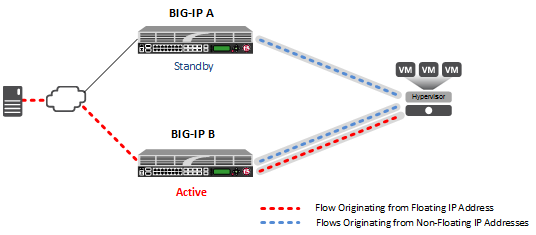
NVGRE tunnels configured for HA pair, after failover
About Microsoft Hyper-V representation of tunnels
The Microsoft Hyper-V uses customer records to represent the associations of overlay addresses with remote tunnel endpoints. This information needs to be statically configured for each overlay address:
- Customer IP address (overlay address)
- Customer MAC address
- Provider IP address (underlay/tunnel endpoint)
- VSID (tunnel key)
- Routing domain
One example of overlay addresses is self IP addresses assigned to NVGRE tunnel objects on the BIG-IP® system. If an address is configured as a floating self IP address, the tunnel local endpoint must also be a floating self IP address. This ensures that failover maintains the validity of the Hyper-V configuration. The traffic groups used for the overlay self IP addresses also need to be configured with a masquerading MAC address.
About configuration of NVGRE tunnels in an HA pair
In an HA configuration, the config sync operation applies, by default, to all tunnel objects on all devices, regardless of whether the tunnel local endpoints are set to floating self IP addresses. This behavior restricts NVGRE tunnels to using only floating self IP addresses, unless you specify a secondary address when you create the tunnel.


