Applies To:
Show Versions
About i800 Series models
The i800 Series platform is a powerful system that is designed specifically for application delivery performance and scalability.
For more information, please see the data sheet at www.f5.com/pdf/products/big-ip-platforms-datasheet.pdf.
About the platform
Before you install this platform, review information about the controls and ports located on both the front and back of the platform.
On the front of the platform, you can use the LCD touchscreen to view information about, manage, and reset the system. You can also use the front-panel LEDs to assess the condition of the system.
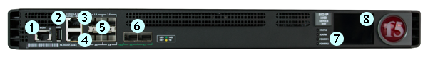
Front view of the i800 Series platform
- 10/100/1000-BaseT capable management port
- Hi-Speed USB port
- Console serial port
- Serial (hard-wired) failover port
- 1GbE SFP ports (4)
- 10GbE SFP+ ports (2)
- Indicator LEDs
- 2.2 inch LCD touchscreen
The back of the i800 Series platform includes one power supply, one power blank, and a chassis ground terminal.

Back view of the i800 Series AC-powered platform
- Power input panel 1 (AC power receptacle)
- Power blank
- Chassis ground terminal
Hardware included with the platform
This platform includes all of the hardware components listed here.
| Quantity | Hardware |
|---|---|
| 1 or 2 | Power cables (black), AC power only, per platform configuration. Might include multiple power cable types if product is delivered outside of the US/Canada. By default, these platforms include one power supply and power cable: i800 Series. |
| 1 | RJ45 to RJ45 failover cable, CAT 5 crossover (blue) |
| 1 | RJ45 to DB9 console port cable (beige) |
| 1 | RJ45F to RJ45M rolled adapter (beige) |
| 1 | Quick-install rail kit |
| 2 | Rail lock brackets |
| 4 | M3 x 6mm flathead screws, black with patch |
| 2 | #8-32 pan head screws, steel zinc |
Peripheral hardware required
For each platform, you might need to provide additional peripheral hardware. If you plan to remotely administer the system, it would be helpful to have a workstation already connected to the same subnet as the management interface.
| Type of hardware | Description |
|---|---|
| Network hubs, switches, or connectors to connect to the platform network interfaces | You must provide networking devices that are compatible with the network interface ports on the platform. You can use 10/100/1000/10000-Megabit switches. |
| External USB CD/DVD drive or USB flash drive | You can use any USB-certified CD/DVD mass storage device or
a USB flash drive for installing upgrades and for system
recovery.
Note: External CD/DVD drives must be
externally powered.
|
| Serial console | You can remotely manage the platform by connecting to a
serial console terminal server through the console port.
Important: In the event that network access is
impaired or not yet configured, the serial console might
be the only way to access the unit. You should perform all
installations and upgrades using the serial console, as
these procedures require reboots, in which network
connectivity is lost temporarily.
|
| Management workstation on the same IP network as the platform | You can use the default platform configuration if you have a management workstation set up. |
About LCD menus
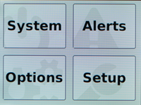
The touchscreen LCD provides the ability to manage the unit without attaching a console or network cable. You can configure the display options to meet your needs. There are four menu options available on the LCD.
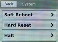
System menu
You can use the System menu to reboot, reset, halt, power off, or power on the system.
| Option | Description |
|---|---|
| Soft Reboot | Performs a graceful reboot of the unit. |
| Hard Reset | Performs a hard reset on the unit. |
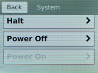
| Halt | Halts or shuts down the unit. |
| Power Off | Powers off the unit. |
| Power On | Powers on the unit. |
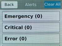
Alerts menu
You can use the Alerts menu to view system alerts by priority, or to clear all alerts from the LCD.
| Option | Description |
|---|---|
| Emergency | Displays alerts that match the Emergency priority. |
| Critical | Displays alerts that match the Critical priority. |
| Error | Displays alerts that match the Error priority. |
| Warning | Displays alerts that match the Warning priority. |
| Alert | Displays alerts that match the Alert priority. |
| Info | Displays alerts that match the Informational priority. |
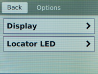
Options menu
You can use the Options menu to configure the LCD brightness and enable/disable the chassis locator LED.
| Option | Description |
|---|---|
| Display | Adjusts LCD backlight brightness. |
| Locator LED | Controls the use of the chassis locator feature, which
causes the F5®
logo ball on the
chassis front panel to flash on and off. Select from these
options:
|
Setup menu
You can use the Setup menu to configure the management interface, AOM management interface, and serial port baud rate.
| Option | Description |
|---|---|
| Management | Changes the management interface information. Select from
these options:
|
| AOM Management | Changes the AOM management interface information. Select
from these options:
|
| Baud Rate | Changes the baud rate of the management serial port. Select
from these options:
|
About using the LCD
To manage the platform using the LCD menu options, tap the touchscreen LCD to put it into menu mode. The LCD is operational even when the Host is powered off, provided that Always-On Management and the LCD are fully booted.
Reboot the unit
-
Touch the screen to activate the LCD menus.
-
Tap System.
The System screen displays.
Reset the unit
-
Touch the screen to activate the LCD menus.
-
Tap System.
The System screen displays.
Halt the unit
-
Touch the screen to activate the LCD menus.
-
Tap System.
The System screen displays.
Power off/on the unit
-
Touch the screen to activate the LCD menus.
-
Tap System.
The System screen displays.
-
On the System screen, swipe to scroll down and tap Power
Off or Power On.
Clear alerts
-
Touch the screen to activate the LCD menus.
-
Tap Alerts.
The Alerts screen displays.
Configure LCD brightness
-
Touch the screen to activate the LCD menus.
-
Tap Options.
The Options screen displays.
-
Tap Display.
The Brightness screen displays.

Enable/Disable the chassis locator LED
-
Touch the screen to activate the LCD menus.
-
Tap Options.
The Options screen displays.
-
Click Locator LED.
The Locator LED screen displays.

About platform LEDs
The behavior of the various LEDs on the platform indicate the status of the system or component.
Status LED
The status LED indicates the operating state of the system.
| State | Description |
|---|---|
| off/none | System is powered down. |
| green solid | System is running in normal mode. Also indicates that the system is in an Active state of a device group. |
| amber solid | System is running in an impaired mode or is operating in
one of these conditions:
|
| amber blinking | System might be in a state in which a software or hardware problem is interfering with control of the LCD or communication is lost between the system and the LCD. |
Alarm LED
The alarm LED indicates system alarm conditions and the severity of the alarm condition.
| State | Description |
|---|---|
| off/none | Informational or no alarm conditions are present. System is operating properly. |
| amber solid | Warning (0). System may not be operating properly, but the condition is not severe or potentially damaging. |
| amber blinking | Error (1). System is not operating properly, but the condition is not severe or potentially damaging. |
| red solid | Alert (2) or Critical (3). System is not operating properly, and the condition is potentially damaging. |
| red blinking | Emergency (4). System is not operating, and the condition is potentially damaging. |
Power 1 and Power 2 LEDs
The Power 1 and Power 2 LEDs on the front of the chassis indicate the general operating state of the power supplies.
| Power 1 state | Power 2 state | Description |
|---|---|---|
| green solid | green solid | Power supply is present and operating properly. Also indicates when the system is in power standby mode. |
| amber solid | amber solid | Power supply is present, but not operating properly. |
| off/none | off/none | No power supply is present. |
Define custom alerts
- The /etc/alertd/alert.conf file defines standard system alerts. Do not edit this file.
- The /config/user_alert.conf file defines custom settings. You should edit only this file.
About platform interfaces
Every platform includes multiple interfaces. The exact number of interfaces that are on the system depends on the platform type.
Each interface on the platform has a set of properties that you can configure, such as enabling or disabling the interface, setting the requested media type and duplex mode, and configuring flow control.
For information about optical transceivers and cable pinouts for this platform, see F5® Platforms: Accessories.
About managing interfaces
You can use the TMOS Shell (tmsh) or the Configuration utility to manage platform interfaces.
View the status of a specific interface using tmsh
View the status of all interfaces using tmsh
View the status of all interfaces using the Configuration utility
About interface media type and duplex mode
All interfaces on the system default to auto-negotiate speed and full duplex settings. We recommend that you also configure any network equipment that you plan to use with the system to auto-negotiate speed and duplex settings. If you connect the system to network devices with forced speed and duplex settings, you must force the speed and duplex settings of the system to match the settings of the other network device.
By default, the media type on interfaces is set to automatically detect speed and duplex settings, but you can specify a media type as well. Use the following syntax to set the media type:
tmsh modify net interface <interface_key> media <media_type> | auto
If the media type does not accept the duplex mode setting, a message appears. If media type is set to auto, or if the interface does not accept the duplex mode setting, the duplex setting is not saved to the /config/bigip_base.conf file.
View valid media types for an interface
Valid media types
This table lists the valid media types for the tmsh interface command.
| 10baseT half | 1000baseLX full |
| 10baseT full | 1000baseCX full |
| 10GbaseER full | 1000baseT half |
| 10GbaseLR full | 1000baseT full |
| 10GbaseSR full | 1000baseSX full |
| 10GbaseT full | 100GbaseSR4 full |
| 10SFP+Cu full | 100GbaseLR4 full |
| 40GbaseSR4 full | auto |
| 40GbaseLR4 full | none |
| 100baseTX half | no-phy |
| 100baseTX full |
About network interface LED behavior
The appearance and behavior of the network interface LEDs on the platform indicate network traffic activity, interface speed, and interface duplexity.
SFP/SFP+ port LED behavior
The appearance and behavior of the SFP/SFP+ port LEDs indicate network traffic activity, interface speed, and interface duplexity.
| State | Description |
|---|---|
| off (not lit) | No link. |
About Always-On Management
The Always-On Management (AOM) subsystem enables you to manage the system remotely using the serial console or SSH, even if the host is powered down. The AOM Command Menu operates independently of the Traffic Management Operating System® (TMOS® ).
You can use the command menu to reset the unit if TMOS has locked up or get access to TMOS directly, so that you can configure it from the command-line interface.
AOM Command Menu options
The AOM Command Menu provides the AOM options for the platform. You can access the AOM Command Menu using either a serial console or SSH.
| Letter | Option | Description |
|---|---|---|
| B | Set console baud rate | Configures the baud speed for connecting to AOM using the serial
console. Select from these options:
|
| I | Display platform information | Displays information about the AOM firmware, bootloader, and management network configuration; chassis serial and part numbers; MAC address; power supply status; LCD status; and power status for the active console. |
| P | Power on/off host subsystem | Powers the host subsystem on or off. |
| R | Reset host subsystem | Resets the host subsystem with a hardware reset.
Important:
F5®
does not recommend using this option under normal circumstances. It does not
allow for graceful shutdown of the system.
|
| N | Configure AOM network | Runs the AOM network configuration utility. This utility enables
you to reconfigure the IP address, netmask, and default gateway used
by AOM. If you use this option while connected using SSH, your session
will be disconnected as a part of the network configuration operation.
Note: This
option is not available when you are connected
using SSH.
|
| S | Configure SSH Server | Sets a session idle timeout (in seconds) for the AOM SSH server. Available values are 0 (no timeout; default value), or between 30 and 86400 (one day). |
| A | Reset AOM | Resets the AOM subsystem. In this case, the system is reset
with a hardware reset.
Important:
F5®
does not recommend using this option under normal circumstances. It does not
allow for graceful shutdown of the system.
|
| Q | Quit menu and return to console | Exits the AOM Command Menu and returns to terminal emulation mode. |


