Manual Chapter : Platform Installation

Applies To:

Show Versions Show Versions
Manual Chapter

About installing the i800 Series platform

After you have reviewed the hardware requirements and become familiar with the i800 Series platform, you can install the unit into a 19-inch rack.

Important: Before you install this platform, review the environmental guidelines to make sure that you are installing the platform into a compatible rack and in the appropriate environment.

About the quick-install rails

The quick-install rails are optimized for installation into square hole cabinets, but can be installed in other cabinet styles, such as round hole cabinets, using the screws provided. The rails are easily converted to mount to either cabinet style.
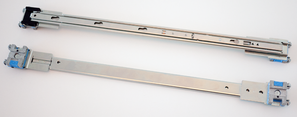
Quick-install rails

For information about installing the platform using the quick-install rails, see the instruction guide provided by the manufacturer, which is included with the rail hardware.

CAUTION:
Be sure that the rotating mount brackets located on the ends of the rails are locked into place on both sides of the platform when installing the quick-install rails.

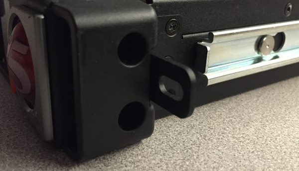
After installing the platform, secure the chassis to the rack with the rail lock brackets that are provided.

Quick-install rail kit hardware

When you are installing with the quick-install rail kit, use these components.

Quantity Hardware
2 Quick-install rails
2 #8-32 pan head screws, steel zinc
8 #8-32 thumb screws (from rail kit, use only when installing into a round hole rack)
2 Rail lock brackets
4 M3 x 6mm flathead screws, black with patch (for rail lock brackets)

Install the rail lock brackets

Be sure that the rails are installed onto the chassis before you install the rail lock brackets.
The rail lock brackets secure the platform to the rack when you are using the quick-install rail kit.
  1. Use a #1 Philips screwdriver to attach the rail lock brackets to each side of the unit using two of the black M3 x 6mm flathead screws that are provided with the kit.
    Use 5 inch-pounds (0.6 Newton-meters) of torque on these screws.
  2. Slide the unit into the rack.
  3. Use a #2 Philips screwdriver to secure the rail lock brackets to the rack on each side of the unit using one of the #8-32 pan head screws that are provided with the kit.
    Use 14 to 16 inch-pounds (1.6 to 1.8 Newton-meters) of torque on these screws.

About grounding the platform

You must ground the platform after you install it in a rack. The chassis ground lug is located on the back of the platform.

Do not secure multiple bonding or grounding connectors with the same bolt. The grounding connectors do not need to be removed to perform service or installation procedures. You can connect other bonding or grounding conductors to a grounding connector provided a reliable bond between the connector and the equipment is not disturbed during installation, service, or maintenance of the platform.
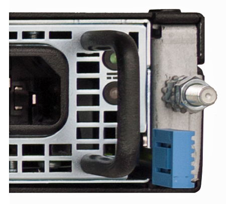
Important: All grounding cable terminal lugs must meet appropriate safety standards.
Note: The platform must be grounded to a common bonding network (CBN).

Chassis ground lug

Connect the ground lug to the ground terminal

You must provide these components to properly ground the chassis:
  • Crimping tool
  • Single ring ground terminal lug
  • One 12 AWG copper wire long enough to reach from the chassis to the common bonding network (CBN)
After the unit is installed in the rack and before you provide power to the system, you need to connect the grounding hardware.
  1. Remove the M5 Keps nuts from the ground lug on the back of the chassis.
  2. Attach a ground ring terminal to the 12 AWG copper ground wire.
  3. Install the ground ring terminal onto the chassis ground terminal.
  4. Secure the ground ring terminal with the M5 Keps nuts.
    Use 18 to 24 inch-pounds (2.0 to 2.7 Newton-meters) of torque on these Keps nuts.
  5. Connect the ground wire to a common bonding network (CBN).

Connect the cables and other hardware

After you have installed the unit into the rack, connect the cables and other hardware.
Important: In the event that network access is impaired or not yet configured, the serial console might be the only way to access the unit. You should perform all installations and upgrades using the serial console, as these procedures require reboots, in which network connectivity is lost temporarily.
  1. If you are using the default network configured on the management interface, connect an Ethernet cable to the management port.
    Note: For EMI compliance, shielded cables are required for the management port, and the shield must be grounded at both ends.
  2. Connect the console port to a serial console server. Depending on which F5® system you have, you can use either the supplied RJ45 to DB9 console port cable or the RJ45F to RJ45M rolled serial adapter to connect the system to a serial console.
    • Connect the RJ45 to DB9 console port cable to the console port on the system.
      Note: The default baud rate and serial port configuration is 19200/8-N-1.
    • Connect the RJ45F to RJ45M rolled serial adapter to the console port if you are connecting the system to a serial console server with a standard CAT5 cable, and then connect the CAT5 cable to the adapter. The adapter provides the appropriate pinout connection to your equipment. For information about cable and connector pinout specifications, see F5 Platforms: Accessories at support.f5.com.

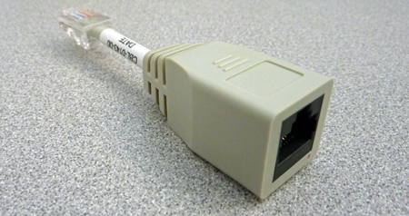
      The RJ45F to RJ45M rolled serial (pass-through) adapter (CBL-0143-00)

  3. Connect power to installed power supplies:
    Note: Be sure to route the power cords away from the fan tray so that the cords do not impede access to it.
    • For AC-powered systems, connect an auto locking power cable to the power input panel on all installed power supplies, and then connect the cable to the power source.
      Note: Not all country-specific power cables include a locking feature.
      Note: To remove the locking power cord, pull one or both of the power cord locking tabs away from the power supply.
  4. If you plan to set up device service clustering (DSC®) with hard-wired failover capacity, connect the serial failover cable to the FAILOVER port on each unit.
    For more information about configuring failover, see BIG-IP® Device Service Clustering: Administration.

You can now assign a management IP address to the system, and then license and provision the software.

Optionally, you should run the latest version of the qkview utility. This utility collects configuration and diagnostic information about your system into a single file that you can provide to F5 Technical Support to aid in troubleshooting. For more information, see:

support.f5.com/kb/en-us/solutions/public/12000/800/sol12878.html

Configure a management IP address using the LCD

You can use the touchscreen LCD to configure the management IP address. With the management IP address, you can access the Configuration utility to configure other aspects of the product, such as the product license, VLANs, and trunks.
Note: When using the LCD to configure the unit, be sure to use the Commit option to save all settings.
  1. Optional: Remove the protective film from the LCD panel using the small cutout on the lower right corner of the film.
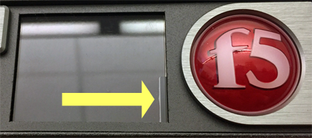
  2. Touch the screen to activate the LCD menus.
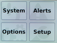
  3. Tap Setup.
    The Setup screen displays.
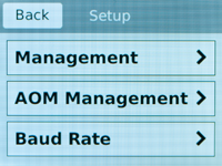
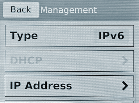
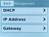
  4. Tap Management.
    The Management screen displays.
  5. For the Type setting, tap to select either IPv4 or IPv6.
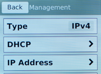
  6. If you are using IPv4, you can configure the management IP address using DHCP:
    1. Tap DHCP.
      The DHCP option displays.
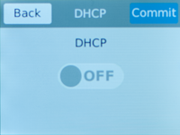
    2. Tap to set the DHCP option to ON.
    3. Tap Commit to save your changes.
  7. If you are using IPv6 or IPv4, you can configure the management IP address manually:
    1. Tap DHCP.
      The DHCP screen displays.
    2. Make sure that the DHCP option is set to OFF.
      If the DHCP option was set to ON, tap OFF, and then tap Commit to save the change.
    3. Tap Back to return to the Management screen.
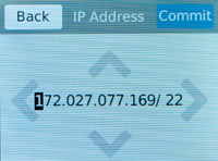
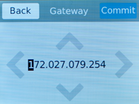
      If you selected IPv4, this screen displays:

      If you selected IPv6, this screen displays:

    4. Tap IP Address.
      The IP Address screen displays.
    5. Use the left, right, up, and down arrows to configure the management IP address and the length of the routing prefix for the IPv4 or IPv6 management IP address.
      For an IPv4 address, this screen displays:

      For an IPv6 address, this screen displays:

    6. Tap Commit to save your changes.
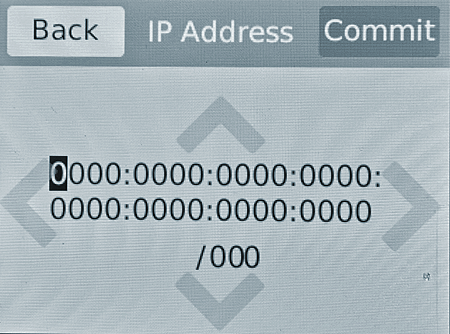
    7. On the Management screen, swipe to scroll down and tap Gateway.
    8. Use the left, right, up, and down arrows to configure the default route for the management interface.
    9. Tap Commit to save your changes.
You can now access the browser-based Configuration utility using the IP address that you configured.

License the platform

Once the management IP address is configured for the platform, you can use the Configuration utility to license the appropriate F5® software.
  1. Using a Web browser, navigate to the management IP address that you assigned to the platform.
    Use this format where <mgmt_ip_address> is the management IP address that you assigned:
    https://<mgmt_ip_address>
    For example, type an IPv4 management IP address like this: https://192.168.0.22. For an IPv6 management address of 2001:0DB8::f5f5/64, type the address like this: https://[2001:0DB8::f5f5].
  2. Type admin as the user name and admin as the password.
    If this is the first time you have accessed the Configuration utility, the first screen you see is the Introduction screen.
  3. Click Next to view the License screen.
  4. Follow the instructions in the Configuration utility to license the platform.