Applies To:
Show Versions
BIG-IP AAM
- 11.6.5, 11.6.4, 11.6.3, 11.6.2, 11.6.1
BIG-IP APM
- 11.6.5, 11.6.4, 11.6.3, 11.6.2, 11.6.1
BIG-IP GTM
- 11.6.5, 11.6.4, 11.6.3, 11.6.2, 11.6.1
BIG-IP Analytics
- 11.6.5, 11.6.4, 11.6.3, 11.6.2, 11.6.1
BIG-IP Link Controller
- 11.6.5, 11.6.4, 11.6.3, 11.6.2, 11.6.1
BIG-IP LTM
- 11.6.5, 11.6.4, 11.6.3, 11.6.2, 11.6.1
BIG-IP PEM
- 11.6.5, 11.6.4, 11.6.3, 11.6.2, 11.6.1
BIG-IP AFM
- 11.6.5, 11.6.4, 11.6.3, 11.6.2, 11.6.1
BIG-IP ASM
- 11.6.5, 11.6.4, 11.6.3, 11.6.2, 11.6.1
Creating an Active-Active Configuration Using the Setup Utility
Overview: Creating a basic active-active configuration
This implementation describes how to use the Setup utility to configure two new BIG-IP® devices that function as an active-active pair. An active-active pair is a pair of BIG-IP devices configured so that both devices are actively processing traffic and are ready to take over one another if failover occurs. The two devices synchronize their configuration data to one another.
Using this implementation, you begin by running the Setup utility on each device to configure its base network components. Base network components include a management port, administrative passwords, and default VLANs and their associated self IP addresses. You also use Setup to configure configuration synchronization and high availability.
You then use the BIG-IP® Configuration utility to:
- Establish trust between the two devices
- Create a Sync-Failover type of device group that contains two member devices
- Create a second traffic group
- Create two iApp™ application services
In this configuration, both devices actively process application traffic, each for a different application. One device processes its application traffic using the configuration objects associated with the default floating traffic group, traffic-group-1. By default, this traffic group contains the floating self IP addresses of the default VLANs. The other device processes its application traffic using a second traffic group that you create.
If one of the devices becomes unavailable for any reason, the other device automatically begins processing traffic for the unavailable peer, while continuing to process the traffic for its own application.
This illustration shows an example of the device group that this implementation creates, named Device Group A. This device group contains two BIG-IP devices, Device 1 and Device 2.
The configuration shows two traffic groups, traffic-group-1 and traffic-group-2, each containing failover objects. For traffic-group-1, Device 1 is the default device. For traffic-group-2, Device 2 is the default device. If Device 1 becomes unavailable, traffic-group-1 floats to Device 2. If Device 2 becomes unavailable, traffic-group-2 floats to Device 1.
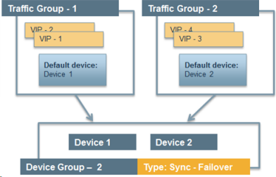
Device group with active-active configuration
By implementing this configuration, you ensure that:
- Each device has base network components configured.
- Any objects on a BIG-IP device that you configure for synchronization remain synchronized between the two devices.
- Failover capability and connection mirroring are enabled on each device.
Task summary
The BIG-IP® configuration process begins with running the Setup utility on each of the two BIG-IP devices. Once you have completed that task, you can log into either of the BIG-IP devices and perform all of the remaining tasks, on that device only. This results in both BIG-IP devices being configured properly for an active-active implementation.
Licensing and provisioning the BIG-IP system
Configuring a device certificate
- Click Import, import a certificate, click Import, and then click Next.
- Verify the displayed information for the certificate and click Next.
Configuring the management port and administrative user accounts
Enabling ConfigSync and high availability
Configuring the internal network
Configuring the external network
Configuring the network for high availability
Configuring a ConfigSync address
Configuring failover and mirroring addresses
Establishing device trust
Before you begin this task, verify that:
- Each BIG-IP® device that is to be part of the local trust domain has a device certificate installed on it.
- The local device is designated as a certificate signing authority.
You perform this task to establish trust among devices on one or more network segments. Devices that trust each other constitute the local trust domain. A device must be a member of the local trust domain prior to joining a device group.
By default, the BIG-IP software includes a local trust domain with one member, which is the local device. You can choose any one of the BIG-IP devices slated for a device group and log into that device to add other devices to the local trust domain. For example, devices Bigip_1, Bigip_2, and Bigip_3 each initially shows only itself as a member of the local trust domain. To configure the local trust domain to include all three devices, you can simply log into device Bigip_1 and add devices Bigip_2 and Bigip_3 to the local trust domain; there is no need to repeat this process on devices Bigip_2 and Bigip_3.
- On the Main tab, click , and then either Peer List or Subordinate List.
- Click Add.
- Type a device IP address, administrator user name, and administrator password for the remote BIG-IP® device with which you want to establish trust. The IP address you specify depends on the type of BIG-IP device:
- If the BIG-IP device is an appliance, type the management IP address for the device.
- If the BIG-IP device is a VIPRION® device that is not licensed and provisioned for vCMP®, type the primary cluster management IP address for the cluster.
- If the BIG-IP device is a VIPRION device that is licensed and provisioned for vCMP, type the cluster management IP address for the guest.
- If the BIG-IP device is an Amazon Web Services EC2 device, type one of the Private IP addresses created for this EC2 instance.
- Click Retrieve Device Information.
- Verify that the certificate of the remote device is correct.
- Verify that the management IP address and name of the remote device are correct.
- Click Finished.
Creating a Sync-Failover device group
Creating an iApp application for the local device
Creating a traffic group for a remote device
Creating an iApp application for a remote device
Forcing a traffic group to a standby state
You perform this task when you want the selected traffic group on the local device to fail over to another device (that is, switch to a Standby state). Users typically perform this task when no automated method is configured for a traffic group, such as auto-failback or an HA group. By forcing the traffic group into a Standby state, the traffic group becomes active on another device in the device group. For device groups with more than two members, you can choose the specific device to which the traffic group fails over.
Syncing the BIG-IP configuration to the device group
Implementation Results
To summarize, you now have the following BIG-IP® configuration on each device of the pair:
- A management port, management route, and administrative passwords defined
- A VLAN named internal, with one static and one floating IP address
- A VLAN named external, with one static and one floating IP address
- A VLAN named HA with a static IP address
- Configuration synchronization, failover, and mirroring enabled
- Failover methods of serial cable and network
- Local IP addresses defined for failover and connection mirroring
- A designation as an authority device, where trust is established with the peer device
- A Sync-Failover type of device group with two members
- The default traffic group named traffic-group-1 with Device 1 as the default device
- An iApp application associated with traffic-group-1
- A traffic group named traffic-group-2 with Device 2 as the default device
- An iApp application associated with traffic-group-2


