Applies To:
Show Versions
BIG-IP AAM
- 13.0.1, 13.0.0
BIG-IP APM
- 13.0.1, 13.0.0
BIG-IP LTM
- 13.0.1, 13.0.0
BIG-IP DNS
- 13.0.1, 13.0.0
BIG-IP ASM
- 13.0.1, 13.0.0
Example: A single-slot LTM guest on a standalone system
The simplest example of the deployment of a vCMP® system is a standalone system configured with one guest that is provisioned to run BIG-IP® Local Traffic Manager™ (LTM®) on a single slot in the VIPRION® cluster.
The following illustration depicts a single-slot, two-core LTM guest on a standalone VIPRION chassis.
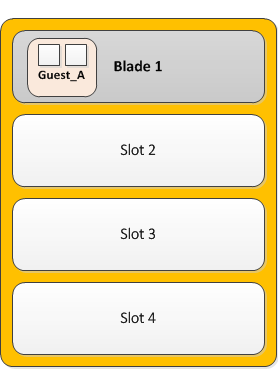
Single-slot, two-core guest on a standalone system
Example: Dual-slot LTM guests within a device group
If you have a redundant system consisting of two VIPRION® chassis, you can deploy a vCMP® guest on each chassis, where each guest is provisioned to run BIG-IP® Local Traffic Manager™ (LTM®) on two slots in the VIPRION cluster.
With this configuration, the host has allocated twice the amount of CPU and memory to the guest than a configuration where the guest is assigned to a single slot only. By putting both guests in a BIG-IP Sync-Failover device group, you are assured that when failover occurs, the LTM guest can continue processing application traffic.
The following illustration depicts the deployment of LTM within a two-slot, four-core guest on each VIPRION chassis in a two-member device group.
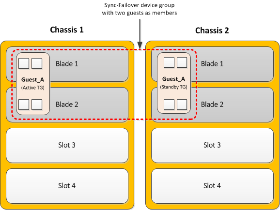
Dual-slot, four-core guests in a device group
Example: Multi-slot guests within device groups
A common use of a vCMP® system is to create a redundant system configuration with multiple guests, where each guest contains a different set of BIG-IP® modules, with varying amounts of system resource allocated to each guest. In this case, the system is in a redundant configuration consisting of two separate VIPRION® systems. For each guest, you can create an equivalent peer guest on the other VIPRION system and create a Sync-Failover device group with the two equivalent guests as members. If failover occurs, the equivalent guest on the peer system can assume the processing of the guest's application traffic.
The following illustration depicts the deployment of BIG-IP guests on multiple populated slots, on two VIPRION chassis. The illustration shows that each guest has an equivalent guest on a peer chassis and that each pair of equivalent guests comprises a separate device group, resulting in a total of four device groups.
Each guest in the first three device groups has either eight, four, or six cores, and spans either four two, or three slots, respectively. The guests in the fourth device group are single-core, single-slot guests.
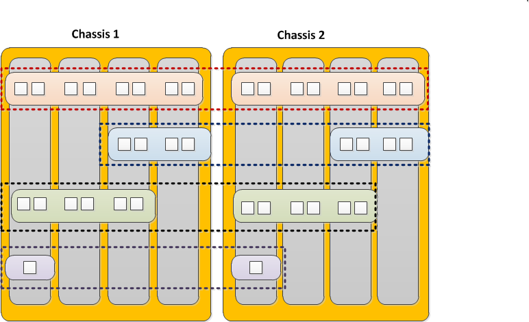
Multiple guests in device groups


