Applies To:
Show Versions
BIG-IQ Centralized Management
- 5.4.0
Which type of centralized management solution do you want to deploy?
There are two license types for a centralized management solution, one for BIG-IQ device management and one for a data collection device (DCD).
BIG-IQ device management
F5® BIG-IQ® Centralized Management is a platform that you use as a tool to help you manage BIG-IP® devices and all of their services (such as LTM®, AFM®, ASM®, and so forth), from one location. BIG-IQ can manage up to 200 (physical, virtual, or vCMP®) BIG-IP devices and handle licensing for up to 5,000 unmanaged devices.
Using BIG-IQ helps you more efficiently manage your BIG-IP devices. That means you and your co-workers don't have to log in to individual BIG-IP systems to get your job done. Instead, you can discover, upgrade, deploy policy changes, manage licenses, and more, from just one place.
From BIG-IQ, you can manage a variety of tasks from software updates to health monitoring, and traffic to security. And because permissions for users are role-based, you can limit access to just a few trusted administrators to minimize downtime and potential security issues. You can also allow users to view or edit only those BIG-IP objects that they need to do their job.
Here's an example of how BIG-IQ can fit into a data center. This topology does not include any DCDs.
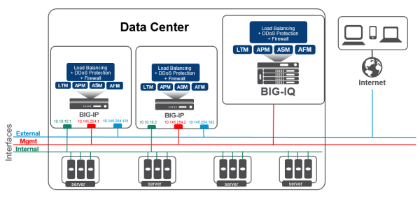
Centralized Management network topology
Data collection device
A data collection device (DCD) is a specially provisioned BIG-IQ system that you use to manage and store alerts, events, and statistical data from one or more BIG-IP systems. The next diagram illustrates a simplified example of how DCDs add to your BIG-IQ Centralized Management solution.
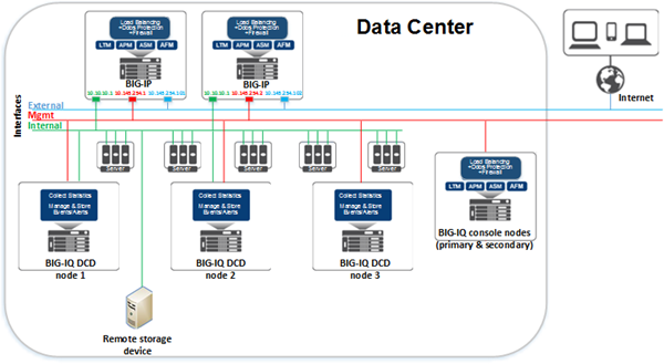
Centralized Management network topology with DCDs
What elements make up a centralized management solution?
- BIG-IQ system(s)
- BIG-IP devices
- Data collection devices (optional)
- Remote storage devices
BIG-IQ Centralized Management system
Using BIG-IQ Centralized Management, you can centrally manage your BIG-IP® devices, performing operations such as backups, licensing, monitoring, and configuration management. And because access to each area of BIG-IQ is role-based, you can limit access to users, thus maximizing work flows while minimizing errors and potential security issues.
BIG-IP device
A BIG-IP device runs a number of licensed components that are designed around application availability, access control, and security solutions. These components run on top of F5® TMOS®. This custom operating system is an event-driven operating system designed specifically to inspect network and application traffic, and make real-time decisions based on the configurations you provide. The BIG-IP software runs on both hardware and virtualized environments.
Data collection device
A data collection device (DCD) is a specially provisioned BIG-IQ system that you use to manage and store alerts, events, and statistical data from one or more BIG-IP systems.
Configuration tasks on the BIG-IP system determine when and how alerts or events are triggered on the client. The alerts or events are sent to a data collection device in a BIG-IQ Centralized Management deployment, and the BIG-IQ system retrieves them for your analysis. When you opt to collect statistical data from the BIG-IP devices, the DCD periodically retrieves those statistics from your devices, and then processes and stores that data.
The group of data collection devices and BIG-IQ systems that work together to store and manage your data are referred to as the data collection cluster. The individual data collection devices are generally referred to as nodes.
Remote storage device
You need a remote storage device only when your deployment includes a data collection device (DCD) and you plan to store backups of your events, alerts, and statistical data for disaster recovery requirements. You also need remote storage so that you can retain this data when you upgrade your software.
Network requirements for a BIG-IQ Centralized Management deployment
Before you deploy a centralized management solution
Before you begin to deploy a BIG-IQ® system, you should complete these preparations.
- Determine the deployment scenario that works best for your needs.
- Create the interfaces, communications, and networks needed to support your deployment scenario.
- Configure your network (including switches and firewalls) to permit BIG-IQ network traffic to flow based on the deployment scenario you choose.
- Assemble the passwords, IP addresses, and licensing information needed for the BIG-IQ cluster components.
Planning for a centralized management deployment
To successfully deploy a BIG-IQ® Centralized Management solution, you might need to coordinate with several people in your company.
If you use BIG-IQ virtual editions, you might need to coordinate with the people who manage your virtual environment, so they can provision the virtual machines with the required amount of CPUs, memory, and network interfaces. Further, you’ll need to coordinate with the people who manage the storage for the virtual machines to make sure each virtual machine is provisioned with the necessary storage to support the BIG-IQ environment. You also might need to provide the virtual environment team a copy of the BIG-IQ virtual machine image (available from https://downloads.f5.com), depending on how they operate.
If you use BIG-IQ 7000 devices in your network, you need to coordinate with the people who manage the data center where the BIG-IQ devices are housed, to make arrangements for the devices to be racked, powered on, and connected to your network.
- IP address allocation for the BIG-IQ nodes, depending on your deployment model.
- Creation of networks, VLANs, and so on, that are dependent on your deployment model.
- Any routing configuration required to ensure that traffic passes between the BIG-IQ nodes and the BIG-IP® devices.
- Additional networking configuration required to support the BIG-IQ system's operation.
Finally, you might need to coordinate with your network firewall administrators, depending on the network configuration at your company. The BIG-IQ software needs to communicate between BIG-IQ nodes and BIG-IP systems; and, if there are firewalls in the network path, firewall rules probably need to be configured to permit that traffic. For additional detail about required network ports and protocols, refer to Open ports required for BIG-IQ system deployment.
Determining the network configuration needed for your deployment
| What functions does your deployment need to perform? | Which hardware components and networks do you need? | Which deployment type should you choose? |
|---|---|---|
| Manage and configure BIG-IP® devices. For example, take backups, license virtual editions, and configure local traffic and security policies. | All you need is one or more BIG-IQ systems, and the BIG-IP devices you want to manage. This configuration uses a single management network. | Simple device management and configuration |
| Manage and configure BIG-IP devices. Collect and view Local Traffic, DNS, and Device statistical data from the BIG-IP devices. Collect, manage, and view events and alerts from BIG-IP devices provisioned with the APM®, FPS, ASM® or IPsec components. |
You need one or more BIG-IQ systems, data collection devices, and an external storage device. This configuration requires a single management network and a data collection device (DCD) cluster network. | Advanced device management and configuration incorporating DCDs |
| Manage and configure BIG-IP devices. Collect and view Local Traffic, DNS, and Device statistical data from the BIG-IP devices. Collect, manage, and view events and alerts from BIG-IP devices provisioned with the APM, FPS, ASM, or IPsec components. Separate network traffic to support large, distributed deployments of the F5 BIG-IQ Centralized Management solution for improved performance, security, and interactions in multiple data center environments. Or, for disaster recovery capability, you could operate multiple data centers, each with its own set of BIG-IQ systems. (For additional detail, refer to Managing Disaster Recovery Scenarios.) |
You need one or more BIG-IQ systems, data collection devices, and an external storage device. This configuration requires an internal network, a management network, and a DCD cluster network. | Large-scale, distributed device management and configuration incorporating DCDs |
Network environment for simple device management and configuration
To deploy a simple device management and configuration environment, all you need is one or more BIG-IQ® systems and the BIG-IP® devices that you want to manage. The number of BIG-IQ systems you need depends on how much redundancy your business requires. A second system provides high availability failover capability.
The simple management and configuration solution uses a single management network. The BIG-IQ system uses traffic on the management network to do these things:
- Enable bidirectional traffic between the BIG-IQ systems and the BIG-IP devices.
- Enable traffic between the BIG-IQ systems. If you use a secondary high availability BIG-IQ system, this traffic keeps the state information synchronized.
- Provide access to the BIG-IQ user interface. You can also use the management network to access the BIG-IQ system using SSH if you need to run manual commands.
This figure illustrates the network topology required for a simple management and configuration deployment.
Simple device management and configuration network topology
Use the space in the table to record the IP address for each device in the BIG-IQ deployment.
| Device type | Management IP address(es) |
|---|---|
| Primary BIG-IQ system | |
| Secondary BIG-IQ system | |
| BIG-IP devices |
Network environment for advanced device management and configuration incorporating DCDs
To deploy the advanced management and configuration environment, you need BIG-IQ® systems, data collection devices (DCDs), and an optional external storage device for backing up alert, event, and statistical data. This configuration needs a single management network and an elastic search cluster network.
The BIG-IQ system uses traffic on the management network to do these things:
- Enable bidirectional traffic between the Big-IQ systems and the Big-IP devices.
- Enable traffic between the BIG-IQ systems. If you use a secondary high availability BIG-IQ system, this traffic keeps the state information synchronized.
- Provide access to the BIG-IQ user interface. You can also use the management network to access the BIG-IQ system using SSH if you need to run manual commands.
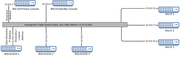
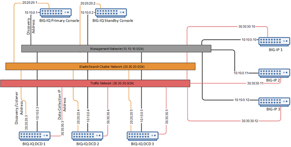
This figure illustrates the network topology required for an advanced management and configuration deployment.
Advanced device management and configuration incorporating DCDs network topology
Use the space in the table to record the IP addresses for the devices in the BIG-IQ deployment.
| Device type | Management IP addresses | Elastic search cluster IP addresses |
|---|---|---|
| Primary BIG-IQ system | ||
| Secondary BIG-IQ system | ||
| Data collection device management IP addresses | ||
| BIG-IP devices | ||
| Remote storage device |
Network environment for large-scale, distributed device management and configuration incorporating DCDs
To deploy a large-scale, distributed management and configuration environment, you need BIG-IQ® systems, data collection devices, and an optional external storage device for backing up alert, event, and statistical data. This configuration needs an internal network, a management network, and an elastic search cluster network.
The BIG-IQ system uses traffic on the management network to do these things:
- Enable traffic between the BIG-IQ systems. If you use a secondary high availability BIG-IQ system, this traffic keeps the state information synchronized.
- Provide access to the BIG-IQ user interface. You can also use the management network to access the BIG-IQ system using SSH if you need to run manual commands.
The internal network is used to route bidirectional traffic between the BIG-IQ Centralized Management cluster and the BIG-IP® devices.
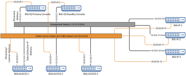
This figure illustrates the network topology required for this deployment.
Large-scale, distributed device management and configuration incorporating DCDs
Use the space in the table to record the IP addresses for the devices in the BIG-IQ deployment.
| Device type | Management IP addresses | Elastic search cluster network IP addresses | Internal network IP addresses |
|---|---|---|---|
| Primary BIG-IQ system | |||
| Secondary BIG-IQ system | |||
| Data collection device management IP addresses | |||
| BIG-IP devices | |||
| Remote storage device |
Determine the resources required for deployment
- Are you deploying a BIG-IQ system or a data collection device (DCD)?
- If you are deploying a DCD, how much storage do you need?
- How much performance do you need?
| Deployment type | CPUs | RAM | Disk Space |
|---|---|---|---|
| BIG-IQ system | 4 | 16 GB | Generally, 95 GB. |
| For higher performance and scale | 8 | 32 or 64 GB | If extra space is needed, 500 GB |
| Data collection device | 4 | 16 GB | Initially: 500 GB. |
| For higher performance and scale: | 8 | 32 or 64 GB | VE disk space can be extended further as needed. |
Open ports required for BIG-IQ system deployment
The BIG-IQ® system and data collection device require bidirectional communication with the devices in your network to successfully manage them. The ports described in the table must be open to allow for this required two-way communication. You might have to contact a firewall or network administrator to verify that these ports are open, or to have them opened if they are not.
| Source IP Address | Destination IP Address | Destination Port | Protocol | Is port Configurable? | Is the Protocol Configurable? | Purpose | Connection Origination |
|---|---|---|---|---|---|---|---|
| Management IP address or external self IP address of the
BIG-IQ.
*See table note 1. |
Management IP address or self IP address of the BIG-IP device. *See table note 1. |
443 (SSL) 22 (SSH) *See table note 4. |
TCP | No | No | Device-level discovery, device configuration changes, and device operations (backup, licensing, and so on), health checking, and some statistics (for example, Access or ADC object status). | From BIG-IQ to BIG-IP devices. |
| Management IP address or external self IP address of the BIG-IQ data collection
device. *See table notes 1 and 2. |
Management IP address or self IP address of the BIG-IP device. *See table note 1. |
443 (SSL) | TCP | No | No | Statistics collection for Local Traffic, Device, and DNS objects. | From BIG-IQ data collection devices to BIG-IP devices. |
| Management IP address or internal self IP address of the
BIG-IQ.
*See table note 1. |
Management IP address or internal self IP address of the
BIG-IQ.
*See table note 1. |
443 (SSL) | TCP | No | No | BIG-IQ cluster synchronization and cluster maintenance. |
From the active BIG-IQ to the standby BIG-IQ. From the BIG-IQ standby to the BIG-IQ active. |
| Management IP address or internal self IP address of the active
BIG-IQ.
*See table note 1. |
Management IP address or internal self IP address of the standby
BIG-IQ.
*See table note 1. |
27017 | TCP | No | No | BIG-IQ high availability cluster data replication. |
From the active BIG-IQ to the standby BIG-IQ. From the BIG-IQ standby to the BIG-IQ active. |
| Internal
self IP address of the
BIG-IQ
and the data collection device. *See table notes 1 and 2. |
Internal
self IP address of the
BIG-IQ
and the data collection device. *See table notes 1 and 3. |
9300 | TCP | Yes | No | Internal node-to-node communication to maintain data consistency and replication across clusters when data collection nodes are used. When you add a DCD to the cluster, this address is called the Data Collection IP Address, | Full Mesh. That is, all BIG-IQ and data collection devices can originate a connection for this purpose. |
| Management IP address or self IP address of the BIG-IP device. *See table note 1. |
Management IP address or self IP address of the BIG-IQ data collection device.
*See table notes 1 and 3. |
8514 | TCP | No | No | Logging profile communication for Web Application Security. This traffic uses the syslog protocol documented in RFC 5424. | From BIG-IP devices to BIG-IQ data collection devices. When you have multiple data collection devices, you need to make sure data can pass to all devices in the cluster. |
| Management IP address or self IP address of the BIG-IP device. *See table note 1. |
Management IP address or self IP address of the BIG-IQ data collection device.
*See table notes 1 and 3. |
8008 | TCP | No | No | Logging profile communication for Fraud Protection Service, this traffic uses the syslog protocol documented in RFC 5424. | From BIG-IP devices to BIG-IQ data collection devices. When you have multiple data collection devices, you need to make sure data can pass to all devices in the cluster. |
| Management IP address or self IP address of the BIG-IP device. | Management IP address or self IP address of the BIG-IQ data collection device.
*See table notes 1 and 3. |
9997 | TCP | No | No | For access to events; this traffic uses the syslog protocol documented in RFC 5424. | From BIG-IP devices to BIG-IQ data collection devices. When you have multiple data collection devices, you need to make sure data can pass to all devices in the cluster. |
| Client IP address | BIG-IQ Management IP address or self IP address for all BIG-IQ instances in the cluster. |
443 (SSL) 22 (SSH) |
TCP | No | No | For management access to BIG-IQ system interface or API (port 443) or shell access to BIG-IQ (port 22). | From the client workstation to the BIG-IQ device. |
Passwords required for BIG-IQ system deployment
To install and configure a BIG-IQ® system or data collection device (DCD) cluster, you use the default passwords for all of the devices. For DCD clusters, if you intend to schedule regular snapshots of your logging data (as recommended), you need root access credentials for the machine on which you plan to store these snapshots.
| User Name | Default Password | Access Rights/Role |
|---|---|---|
| admin | admin | This user type can access all aspects of the BIG-IQ system from the system's user interface. |
| root | default | This user has access to all aspects of the BIG-IQ system from the system's console command line. |
Licenses required for BIG-IQ system deployment
To install and configure a BIG-IQ system or data collection device cluster, you need a license for each device.
BIG-IQ Centralized Management Deployment
How do I deploy a BIG-IQ system?
To manage your BIG-IP® devices using BIG-IQ® Centralized Management, you deploy a BIG-IQ system and then configure it to meet your business needs.
- Prepare your network environment
- Deploy a BIG-IQ virtual machine or BIG-IQ 7000 Series platform
- License and configure the BIG-IQ system
- Deploy and configure a second BIG-IQ system for HA, if needed.
How do I license and do the basic setup to start using BIG-IQ?
After you download the software image from the F5 Downloads site and start BIG-IQ® in your virtual environment, you can license the system using the base registration key provided by F5. The base registration key is a character string the F5 license server uses to provide BIG-IQ a license to access the subscription licensing feature.
You license BIG-IQ in one of the following ways:
- If the system has access to the Internet, you can have the BIG-IQ system contact the F5 license server and automatically activate the base registration key to get a license.
- If the system is not connected to the Internet, you can manually license the BIG-IQ using the F5 license server web portal.
- If the system is in a closed-circuit network (CCN) that does not allow you to export any encrypted information, you must open a case with F5 support at: support.f5.com/csp/my-support/home.
When licensing BIG-IQ, you:
- Activate the license.
- Accept the EULA.
- Specify the system personality as BIG-IQ Centralized Management.
- Specify a host name, and IP addresses for the management port, DNS server, and network time protocol (NTP) servers.
- Specify the master key pass phrase.
- Change the default admin and root passwords.
Automatic license and initial setup for a BIG-IQ
Manual license and initial setup for BIG-IQ
BIG-IQ Data Collection Device Deployment
How do I deploy a data collection device cluster?
To manage the data generated by BIG-IP® devices on BIG-IQ® Centralized Management, you deploy a network of devices called a data collection device (DCD) cluster, and then configure that cluster to meet your business needs.
- Prepare your network environment.
- Install the DCDs.
- Discover and activate the DCDs.
- Define an external location to store snapshots.
- Enable data collection for the DCD cluster (or configure a BIG-IP system to send alerts or events to the cluster).
- Configure the BIG-IQ console that manages the DCD cluster for HA, if needed.
Licensing and setting up a data collection device
The BIG-IQ® data collection device runs as a virtual machine in supported hypervisors, or on the BIG-IQ 7000 series platform. You license the data collection device using the base registration key you purchased. The base registration key is a character string that the F5 license server uses to provide access to data collection device features.
You license data collection device in one of the following ways:
- If the system has access to the internet, you can have the data collection device contact the F5 license server and automatically activate the license.
- If the system is not connected to the internet, you can manually retrieve the activation key from a system that is connected to the internet, and transfer it to the data collection device.
- If your data collection device is in a closed-circuit network (CCN) that does not allow you to export any encrypted information, you must open a case with F5 support.
When you license the data collection device, you:
- Specify a host name for the system.
- Assign a management port IP address.
- Specify the IP address of your DNS server and the name of the DNS search domain.
- Specify the IP address of your Network Time Protocol (NTP) servers and select a time zone.
- Change the administrator’s default admin and root passwords.
Automatic license and initial setup for a DCD
Manual license and initial setup for a DCD
Discover and activate a data collection device
Deciding whether to configure log indices
- A new current index is created.
- BIG-IP data begins accumulating in the new index.
- The former current index becomes one of the retained indices.
- If the total number of indexes is now larger than the retained index count, the oldest one is dropped.
Modify alert log indices for Access
Modify alert log indices for Web Application Security
Modify event log indices for FPS
Modify alert log indices for IPsec
Manage the retention policy for your statistics data
- The number of BIG-IP® devices you manage
- The number of objects on the BIG-IP devices you manage (for example, virtual servers, pools, pool members, and iRules®)
- The frequency of statistics collection
- The data retention policy
- The data replication policy
| How long is data in each container retained? | Data is retained in each container for the time period you specify. When the specified level is reached, the oldest chunk of data is deleted. For example, if you specify a raw data value of 48 hours, then when 48 hours of raw data accumulate, the next hour of incoming raw data causes the oldest hour to be deleted. |
| When does data from one container pass on to the next? | Data passes from one container to the next in increments that are the size of the next (larger) container. That is, every 60 minutes, the last 60 minutes of raw data is aggregated into a data set and passed to the Hour(s) container. Every 24 hours, the last 24 hours of hourly data is aggregated into a data set and passed to the Day(s) container, and so on for the Month(s) container. |
| What about limits? |
Limit Max Storage to specifies the
percentage of total disk space that you want data to consume on the
data collection devices in your cluster. If more disk space is consumed than the percentage you specified, BIG-IQ takes two actions:
|
Configure secure communications for data collection device
- Use SSH to log in to the data collection device.
- Replace the content of the /etc/httpd/conf/ssl.crt/ directory on the data collection device with your signed SSL certificate.
- Replace the content of the /etc/httpd/conf/ssl.key/ directory on the data collection device with your signed SSL key.
- To apply these changes to the data collection device, type: bigstart restart webd and then press Enter.
- Log out of the data collection device.
Add a proxy for secure communication
Before you can perform this task, you must be logged in as Admin, and you must have configured a proxy server that your data collection device cluster can access.
Define external storage snapshots location
- IP address for the storage machine
- Storage file path
- User name, password, and (optionally) domain for the user account configured on the external storage device
- Read/Write permissions for the storage file path
If you set up external storage for this logging node cluster in 5.1.and plan to retain that setup after you upgrade, continue setting up the external storage location. When you create DCD snapshots, they need to be stored on a machine other than the DCD. You define the location for the snapshot using the BIG-IQ® Centralized Management device.
Define snapshot schedules
Overview of configuring the data collection device to BIG-IP device connection
The workflow to configure data to route from the BIG-IP® devices to your data collection device (DCD) cluster depends on the type of data you want to collect.
- To collect statistics data, refer to Discover and activate a data collection device.
- To collect Access Policy Manager® data, refer to Configuring remote logging for Access Policy Manager.
- To collect Fraud Protection Services data, refer to Configuring BIG-IP FPS devices to route alerts to a data collection device.
- To collect Web Application Security
data, refer to:
- Configuring the BIG-IP logging profile
- Virtual servers that remote logging uses to route event logs
- Assigning the logging profile to a virtual server
Configure remote logging for Access Policy Manager
Configuring BIG-IP FPS devices to route alerts to a data collection device
The BIG-IP® device that generates Fraud Protection Service alerts must be configured to send its alerts to the data collection device (DCD). This process is documented in a separate guide. The guide F5® Fraud Protection Service: Configuration, Version 13.0 provides complete setup instructions for using FPS on a BIG-IP® system. Complete the standard setup as documented in the guide, except when you configure the alert server pool, add your DCDs to an alerts pool using their internal self IP addresses.
- Distribute traffic between the nodes.
- Ensure that, if a DCD goes offline, the BIG-IP device must still be able send traffic to the available DCDs without dropping alerts.
The default port to specify is 8008, but you can use a different port if your DCD is configured for it. To ensure that alerts are received even if one DCD goes down, specify at least one alternative DCD.
Configure the BIG-IP logging profile
Virtual servers that remote logging uses to route alert or event logs
You can either create a new virtual server on the BIG-IP® device that creates the alert or event, or you can use a virtual server that already exists on that device.
Creating a virtual server for remote logging
Assign the logging profile to a virtual server
Data collection device sizing guidelines
The number of devices of each type that will best meet your company's needs depends on a number of factors. Refer to the F5 BIG-IQ Centralized Management: Data Collection Device Sizing Guide on support.f5.com for details.


