Updated Date: 07/07/2026
Configuring SIP Load Balancing
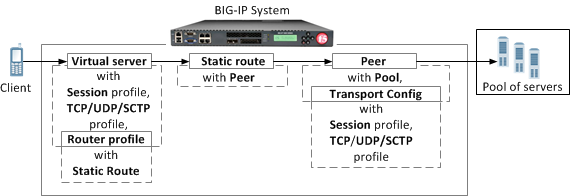
You can use the BIG-IP system as a Session Initiation Protocol (SIP) proxy. When the BIG-IP system is placed between your SIP routers, session border controllers, and soft switches, you can configure the system to route and load balance SIP messages across the servers on your SIP network.
This graphic illustrates the relationships of the configuration objects that you must configure on the BIG-IP system.
Through the SIP Session Profile, you can use Message Routing Framework (MRF) to manage SIP traffic across pool members by means of configuring and using Via headers. When you configure Via headers to manage SIP traffic, dependencies between settings apply, enabling you to steer traffic and control requests and responses, as necessary.
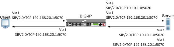
Note: When a client Via header only specifies an address, without specifying a port, the BIG-IP system uses default port 5060. For example, if a client sends a request with Via header SIP/2.0/TCP 192.168.20.1, in SIP session traffic scenario 1 (default), the BIG-IP system sends a response to the client with Via header SIP/2.0/TCP 192.168.20.1/5060.
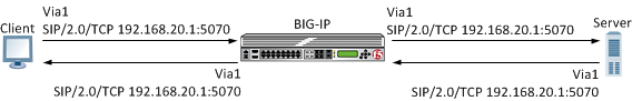
In SIP session traffic scenario 1 (default), the BIG-IP system receives a request with a Via1 header from a client, and inserts a Via2 header into the request before forwarding the request to the server. When the server provides a response, the BIG-IP system removes the Via2 header from the response, before forwarding the response to the client. If the originating connection no longer exists, the Via2 header that BIG-IP system inserted is no longer available; consequently, the BIG-IP system uses the Via1 header, forwarding the message to the client IP address and port specified by that Via header.
When configuring this scenario, the following SIP Session Profile settings apply.
| SIP Session Profile control | Setting or value |
|---|---|
| Honor Via | Enabled |
| Do Not Connect Back | Disabled |
| Insert Via Header | Enabled |
| Custom Via | Not applicable |
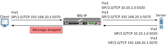
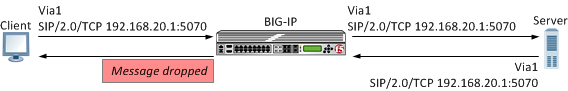
In SIP session traffic scenario 2, the BIG-IP system receives a request with a Via1 header from a client, and inserts a Via2 header into the request before forwarding the request to the server. When the server provides a response, the BIG-IP system removes the Via2 header from the response, before forwarding the response to the client. When the originating connection no longer exists, then the BIG-IP system drops the response message and increments the statistic for Messages failed due to connection dropped.
When configuring this scenario, the following SIP Session Profile settings apply.
| SIP Session Profile control | Setting or value |
|---|---|
| Honor Via | Enabled |
| Do Not Connect Back | Enabled |
| Insert Via Header | Enabled |
| Custom Via | Not applicable |
In SIP session traffic scenario 3, the BIG-IP system receives a request with a Via1 header from a client, and inserts a Via2 header into the request before forwarding the request to the server. When the server provides a response, the BIG-IP system removes the Via2 header from the response, before forwarding the response to the client. If the originating connection no longer exists, then the Via header that BIG-IP system inserted is no longer available; consequently, the BIG-IP system uses the next available Via header, but, because the Honor Via setting is Disabled, the BIG-IP system does not forward the message to the client IP address and port specified by that Via header.
When configuring this scenario, the following SIP Session Profile settings apply.
| SIP Session Profile control | Setting or value |
|---|---|
| Honor Via | Disabled |
| Do Not Connect Back | Disabled |
| Insert Via Header | Enabled |
| Custom Via | Not applicable |
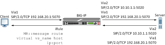
In SIP session traffic scenario 4, the BIG-IP system receives a request with a Via1 header from a client, and inserts a Via2 header into the request before forwarding the request to the server. When the server provides a response, the response from the BIG-IP to the client must be managed by means of an iRule, for example, MR::message nexthop TMM:flow_id or MR::message route virtual vs_name host ip:port.
When configuring this scenario, the following SIP Session Profile settings apply.
| SIP Session Profile control | Setting or value |
|---|---|
| Honor Via | Not applicable |
| Do Not Connect Back | Not applicable |
| Insert Via Header | Enabled |
| Custom Via | Custom Via header value, for example: SIP/2.0/TCP www.siterequest.com:4343 or SIP/2.0/SCTP 10.10.4.32 |
In SIP session traffic scenario 5, the BIG-IP system receives a request with a Via1 header from a client, but does not insert a Via header into the request before forwarding the request to the server. When the server provides a response, the BIG-IP system uses the client Via1 header in the response to forward the message to the client IP address and port specified by that Via header.
When configuring this scenario, the following SIP Session Profile settings apply.
| SIP Session Profile control | Setting or value |
|---|---|
| Honor Via | Enabled |
| Do Not Connect Back | Not applicable |
| Insert Via Header | Disabled |
| Custom Via | Not applicable |
In SIP session traffic scenario 6, the BIG-IP system receives a request with a Via1 header from a client, but does not insert a Via header into the request before forwarding the request to the server. Instead, the BIG-IP system uses the Via1 header specified in the request. When the server provides a response, the BIG-IP system uses the Via1 header in the response, but does not forward the message to the client IP address and port specified by that Via header.
When configuring this scenario, the following SIP Session Profile settings apply.
| SIP Session Profile control | Setting or value |
|---|---|
| Honor Via | Disabled |
| Do Not Connect Back | Not applicable |
| Insert Via Header | Disabled |
| Custom Via | Not applicable |
This table names and describes the objects necessary to configure the BIG-IP system as a SIP proxy.
| Configuration Objects | Description |
|---|---|
| Session Profile | Defines how BIG-IP processes SIP messages, including the data used to persist SIP connections. |
| Transport config | Defines how BIG-IP connects with the servers on your SIP network. |
| Pool | Defines how BIG-IP load balances connections across a group of servers. |
| Peer | Defines how BIG-IP connects with the servers on your network and to which servers the system routes and load balances SIP messages. |
| Static route | Defines how BIG-IP routes SIP messages. |
| Router profile | Defines an instance of a SIP router. |
| Virtual Server | Defines the destinations in your network, including the servers that process incoming SIP requests and the pool members that process connections between BIG-IP and your SIP network. |
Complete these tasks to configure SIP message routing on a system.
Create a SIP session profile to define how the BIG-IP system processes SIP messages, including the data the system uses to persist SIP connections.
-
On the Main tab, click Local Traffic > Profiles > Message Routing > SIP.
The SIP transport config list screen opens.
-
On the menu bar, click Session Profiles.
The Session Profiles list screen opens.
-
Click Create.
The New SIP Session Profile screen opens.
-
In the Name field, type a unique name for the SIP session profile.
-
From the Persist Key list, select the value the system uses for persistence of a SIP session. The options are:
Option Description Call-ID The system uses the value in the Call-ID header field in the SIP message. Custom The system uses the value of a custom key specified in an iRule. Src-Addr The system uses the originating IP address in the SIP message. -
From the Persist Type list, select one of these options:
Option Description Session Persistence is enabled. None Persistence is disabled. -
In the Persist Timeout (seconds) field, type the number of seconds before a SIP session persistence record expires.
-
Click Finished.
Ensure that at least one SIP session profile exists in the BIG-IP system configuration.
Create a transport config to define how the BIG-IP system connects with the servers on your network when routing and load balancing SIP messages.
-
On the Main tab, click Local Traffic > Profiles > Message Routing > SIP.
The SIP session profiles list screen opens.
-
On the menu bar, click Transport Config.
The New Transport Config screen opens.
-
Click Create.
-
In the Name field, type a unique name for the transport config.
-
For the Profiles setting, move both a transport protocol profile (TCP, UDP, or SCTP) and a SIP session profile from the Available list to the Selected list.
You can associate only one protocol profile and one SIP session profile with each transport config.
-
Click Finished.
In order to create a peer, you must first ensure that at least one transport configuration and one pool exist in the BIG-IP system configuration.
You create a peer to define how the BIG-IP system connects with the servers on your network, and to which servers the system routes and load balances messages.
-
On the Main tab, click Local Traffic > Profiles > Message Routing > Diameter.
The Diameter Session Profiles list screen opens.
-
On the menu bar, click Peers.
The Peers list screen opens.
-
Click Create.
The New Peer screen opens.
-
Type a unique Name for the peer.
-
Type a Description of the peer.
-
From the Connection Mode list, select an option to specify how connections are distributed to a remote host.
Option Description Per Blade The number of connections is distributed and controlled per blade on a VIPRION system. Per Peer (Default) The number of connections to a remote host is per peer. Per TMM The number of connections to a remote host is per TMM on the BIG-IP system. Per Client The number of connections to a remote host is per client connection. Responses are delivered to the connection initiating the request. This option is typically used when implementing a firewall, because of its restrictive functionality. Note: The configured Connection Mode, Number of Connections, and Ratio settings determine how the BIG-IP system uses connections to pool members in delivering messages.
-
From the Pool list, select the pool of servers to which the system load balances Diameter messages.
In the case where the calls should be always sent to a single SIP Server, you will still need to create a pool with a single member (the SIP Server) and add the same to the peer.
-
From the Transport Config list, select the transport configuration that defines the egress message routing peer connection.
-
In the Number of Connections box, type the number of allowed connections between the BIG-IP system and the servers in the selected pool.
-
For Ratio, type the ratio assigned to this peer for use within a static route.
-
Click Finished.
A peer determines how the BIG-IP system connects with the servers on your network, and to which servers the system routes and load balances messages.
Ensure that at least one peer and one virtual server exist in the BIG-IP system configuration.
Create a static route when you want to route SIP messages from specific clients to specific domains, and load balance those SIP messages across a group of peers. If the configured attributes of a static route match the attributes in a SIP message, the system forwards the message to a member of the pool associated with one of the peers.
Note: The BIG-IP system can use multiple SIP session profiles in a single routing instance, because a different profile can be associated with each member of a pool.
-
On the Main tab, click Local Traffic > Profiles > Message Routing > SIP.
The SIP session profiles list screen opens.
-
On the menu bar, click Static Routes.
The Static Routes list screen opens.
-
Click Create.
The New Route screen opens.
-
In the Name field, type a unique name for the static route.
-
In the Request URI field, type the value found in the request-uri of a SIP message that the system matches when routing a message.
-
In the From URI field, type the value found in the From field of a SIP message that the system matches when routing a message.
-
In the To URI field, type the value found in the To field of a SIP message that the system matches when routing a message.
-
From the Virtual Server list, select the virtual server from which the system receives client requests for this static route.
If you do not select a virtual server, the system uses this static route to route SIP messages originating from any client.
-
From the Peer Selection Mode field, select how the system selects the Peer to route a SIP message to:
Option Description Ratio Peer selection is based on the ratio that is set for each peer in the Selected list. Sequential Peer selection is based on the order of the peers in the Selected list. -
For the Peers setting, move the peers that define the servers to which the system load balances SIP messages from the Available list to the Selected list.
-
Click Finished.
Before you start this task, ensure that at least one static route exists on the BIG-IP system.
Create a SIP router profile to define how a router handles SIP traffic.
Note: A SIP routing profiles binds the virtual server that processes SIP requests from clients with the peers that connect with the servers on your SIP network.
-
On the Main tab, click Local Traffic > Profiles > Message Routing > SIP.
The SIP transport config list screen opens.
-
On the menu bar, click Router Profiles.
The Router Profiles list screen opens.
-
Click Create.
The New SIP Router Profile screen opens.
-
In the Name field, type a unique name for the SIP router profile.
-
In the Settings area, select the Custom check box.
-
From the Operation Mode list, select Load Balancing.
-
To use connection mirroring, configure the Traffic Group setting.
-
Clear the Inherit traffic group from current partition / path check box.
-
From the list, select a traffic group, such as, traffic-group-1.
Important: Changing traffic groups, with Connection Mirroring enabled, drops all mirrored connections and loses all persistence data. If you change traffic groups, mirroring must restart.
Note: The traffic group for the virtual address and mirrored attribute are overwritten by the attached router profile.
-
-
Select the Connection Mirroring check box.
Note: For connection mirroring to properly function, this device must be a member of a device group.
-
In the Mirrored Message Sweeper Interval field, type the milliseconds for the frequency of the mirrored message sweeper.
-
For the Static Routes setting, move routes that define how the BIG-IP system load balances SIP traffic from the Available list to the Selected list.
-
Click Finished.
Ensure that both a SIP session profile and a SIP router profile exist in the BIG-IP system configuration.
Create a virtual server to handle SIP client requests.
-
On the Main tab, click Local Traffic > Virtual Servers.
The Virtual Server List screen opens.
-
In the Name field, type a unique name for the virtual server.
-
From the Type list, select Message Routing.
-
In the Destination Address/Mask field, type an address, as appropriate for your network.
The supported format is address/prefix, where the prefix length is in bits. For example, an IPv4 address/prefix is
10.0.0.1or10.0.0.0/24, and an IPv6 address/prefix isffe1::0020/64or2001:ed8:77b5:2:10:10:100:42/64. When you use an IPv4 address without specifying a prefix, the BIG-IP system automatically uses a/32prefix. -
In the Service Port field, type
5060to route SIP traffic or5061to route TLS traffic. -
From the Configuration list, select Advanced.
-
From the Application Protocol list, select SIP.
-
From the Session Profile list, select a SIP session profile.
-
From the Router Profile list, select a SIP router profile.
-
Click Update.
This table names and describes the objects necessary to configure the BIG-IP system as a SIP proxy.
| Configuration Objects | Description |
|---|---|
| Session Profile | Defines how BIG-IP processes SIP messages, including the data used to persist SIP connections. |
| Transport config | Defines how BIG-IP connects with the servers on your SIP network. |
| Pool | Defines how BIG-IP load balances connections across a group of servers. |
| Peer | Defines how BIG-IP connects with the servers on your network and to which servers the system routes and load balances SIP messages. |
| Static route | Defines how BIG-IP routes SIP messages. |
| Router profile | Defines an instance of a SIP router. |
| Virtual Server | Defines the destinations in your network, including the servers that process incoming SIP requests and the pool members that process connections between BIG-IP and your SIP network. |
You can configure the BIG-IP system to monitor pool member health using a SIP monitor. Use a SIP monitor to check the health of a host with an active SIP session. The SIP monitor also monitors a SIP connection independent of a specific SIP session and marks a host that had been marked down, but is online again, as available.
Create a SIP monitor to mark a pool member as down when that server stops responding and then to mark the pool member as available when service is restored.
-
On the Main tab, click Local Traffic > Monitors.
The Monitors List screen opens.
-
Click Create.
The New Monitor screen opens.
-
In the Name field, type a name for the monitor.
-
From the Type list, select SIP.
The screen refreshes, and displays the configuration options for the SIP monitor type.
-
Configure additional settings based on your network requirements.
-
Click Finished.
Add health monitors to a pool when you want the BIG-IP system to monitor the health of the pool members. Repeat this procedure for each desired pool.
-
On the Main tab, click Local Traffic > Pools.
The Pool List screen opens.
-
Click the name of the pool you want to modify.
-
For the Health Monitors setting, in the Available list, select a monitor type, and click << to move the monitor to the Active list.
Tip: Hold the Shift or Ctrl key to select more than one monitor at a time.
-
Click Finished.
The new pool appears in the Pools list.
You can view statistics for SIP sessions and routes.
Ensure that at SIP session router profile are assigned to at least one virtual server.
When you want to see how the BIG-IP system is handling SIP communications, you can view statistics per SIP session profile.
-
On the Main tab, click Statistics > Module Statistics > Local Traffic.
The Local Traffic statistics screen opens.
-
From the Statistics Type list, select Profiles Summary.
-
In the Details column for the SIP Session profile, click View to display detailed statistics about SIP sessions.
Ensure that at SIP session and SIP router profile are assigned to at least one virtual server.
When you want to see how the BIG-IP system is handling SIP message routing, you can view statistics per SIP router profile.
-
On the Main tab, click Statistics > Module Statistics > Local Traffic.
The Local Traffic statistics screen opens.
-
From the Statistics Type list, select Profiles Summary.
-
In the Details column for the SIP Router profile, click View to display detailed statistics about the routing of SIP messages.