Applies To:
-
BIG-IP APM
21.0.0, 17.5.1, 17.5.0, 17.1.3, 17.1.2, 17.1.1, 17.1.0
-
BIG-IP Link Controller
21.0.0, 17.5.1, 17.5.0, 17.1.3, 17.1.2, 17.1.1, 17.1.0
-
BIG-IP LTM
21.0.0, 17.5.1, 17.5.0, 17.1.3, 17.1.2, 17.1.1, 17.1.0
-
BIG-IP AFM
21.0.0, 17.5.1, 17.5.0, 17.1.3, 17.1.2, 17.1.1, 17.1.0
-
BIG-IP ASM
21.0.0, 17.5.1, 17.5.0, 17.1.3, 17.1.2, 17.1.1, 17.1.0
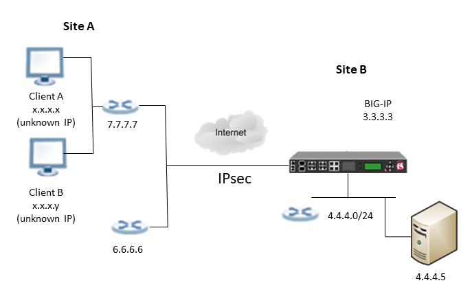
Configuring IPsec in Tunnel Mode between a Remote Device and BIG-IP using Dynamic Template
Before dynamic templates, the IPsec configuration is static and specific to each remote peer identified by its IP address. With the introduction of dynamic template in IKEv2, one configuration can be used for multiple remote peers without information about their IP addresses in advance.
The BIG-IP can establish an IPsec tunnel with dynamic IP addresses that are not configured in the BIG-IP configuration, for example, IP addresses associated with a small cell security gateway. The dynamic template configuration applies to more than one remote peer, by factoring the details that might vary from peer to peer. A single dynamic template IKE peer can be used to support multiple remote peers, at different IP addresses, or different ports behind a single NAT firewall IP address.
The IPsec IKEv2 tunnel can be established with unknown or dynamic endpoints with or without Network Address Translation (NAT) environment. If a NAT firewall is present, then every remote peer appears to have the same IP address because only one IP address is used by the firewall. The port number is used to distinguish each peer. In order to handle more than one remote peer at the same firewall IP address, change the value of system db variable ipsec.port.identity to one. Following is an example command to modify the variable:
tmsh modify sys db ipsec.port.identity value 1This controls whether port is considered part of the identity of IKE peer, in addition to the IP address used by the remote peer.
Only one dynamic template can be created per local IP address used on the BIG-IP. For example, in IPsec policy the Tunnel Local Address setting which is typically the same IP address as the Presented ID Value (my-id-value) attribute in IKE peer. This local tunnel endpoint IP address will have an IPsec listener added to it.
The ip-macro attribute distinguishes an IKE peer as a dynamic template. Each IKE peer requires a dedicated traffic-selector and IPsec policy. The ip-macro attribute in IKE peer means the triple: ike-peer, traffic-selector, and ipsec-policy is a template.
Variables within ip-macro allow configuration generalization by replacing placeholder values. The ip-macro attribute has up to three placeholder values: peer-ip, peer-port, and/or dynamic-ip. For all three, the values act as variables. Wherever placeholder values for these appear in configuration, they will be replaced with the actual values when a tunnel is negotiated. For example, the peer’s IP address can be represented as a Martian IP address (from subnet 192.0.2.x) which acts as a variable. When peer-ip=192.0.2.1 appears inside ip-macro, this means 192.0.2.1 is a variable that acts as a placeholder for the actual peer IP address seen at negotiation time. During IKE negotiation, configuration will be generated that replaces the 192.0.2.1 with the peer’s actual IP address. The notation in ip-macro declares the variables.
Note: The schema requires an IP address, so a Martian IP address like 192.0.2.1 is used to satisfy the syntax requirements. This approach avoids using the <peer-ip> variable, which would be considered invalid in terms of syntax.
Following are examples for attribute ip-macro:
net ipsec ike-peer <peer-name> {
    ...
    ip-macro="peer-ip=192.0.2.1 peer-port=234"
    peers-id-value 192.0.2.1
    my-id-value <BIG-IP address>
    remote-address 192.0.2.1
    ...
}net ipsec ike-peer <peer-name> {
...
ip-macro="peer-ip=192.0.2.1 peer-port=234 dynamic-ip=192.0.2.13"
remote-port 234
address-list '<IP address list value>'
peers-id-value 192.0.2.1
my-id-value <BIG-IP address>
remote-address 192.0.2.1
...
}Note: The Presented ID Value (my-id-value) and the Verified ID Value (peers-id-value) settings are mandatory configuration elements for IKEv2 tunnels. Configure these settings to maintain reliable IPsec connectivity between a BIG-IP system and a remote device.
The value of peer-ip inside ip-macro defines the IP address that acts as a placeholder for a remote peer’s IP address. For example, if the peer-ip is 192.0.2.1, then everywhere 192.0.2.1 appears, the system replaces this with the remote peer’s actual IP address which acts as the tunnel remote endpoint address.
Note: The peer-ip can be any IP address from the Martian IP addresses in the 192.0.2.x subnet, as these addresses will never be used by real devices and the subnet is reserved for example documentation only.
The remote-port variable is used to specify the remote peer’s port number, the template value declares 234 as a placeholder for the actual peer-port. The peer-port is useful for NAT when more than one remote peer can appear behind the same firewall IP address. The actual source port number is substituted where 234 appears as the value of a port.
Note: The peer-port can be any value from the reserved port numbers. According to IANA port number assignments, ports 225 to 241 are reserved and therefore can be used as dummy placeholder values.
The dynamic-ip variable is only used when the remote peer requests for an allocated IP address. This variable is a prediction that the remote peer will always request for an allocated IP, which will get allocated from the address-list attribute in the IKE peer.
If the peer-ip is 192.0.2.1, dynamic-ip is 192.0.2.13, and peer-port is 234, then 192.0.2.1 is a placeholder variable for the peer’s actual IP address, 192.0.2.13 is a placeholder variable for an IP address allocated by the BIG-IP from an address pool, and 234 is a placeholder value for the peer’s actual port number.
Use the destination-ip placeholder in a traffic selector to protect traffic through a tunnel using an allocated address. The following conditions must be met:
-
The remote peer intends to use an allocated address for traffic protected by a tunnel.
-
The IKE peer has an
address-listattribute to define an address pool for IP allocation. -
The IKE peer has an
ip-macrothat declares adynamic-ipvariable like192.0.2.13.Note: It is recommended to only use
192.0.2.13for dynamic IP address.
When all these conditions are met, the IKE peer will allocate an IP address from the address pool defined in address-list, and substitute that address for the placeholder value wherever it appears.
Before you begin configuring IPsec, verify that these modules, system objects, and connectivity exist on the BIG-IP in both the local and remote locations:
- BIG-IP Local Traffic Manager
- This module directs traffic securely and efficiently to the appropriate destination on a network.
- Self IP address
- Each BIG-IP must have at least one self IP address, to be used in specifying the ends of the IPsec tunnel.
- The default VLANs
- These VLANs are named
externalandinternal. - BIG-IP connectivity
- Verify the connectivity between the client or server and its BIG-IP device, and between each BIG-IP device and its gateway. For example, you can use
pingto test this connectivity.
Following is the list of tasks to complete the configuration:
- Creating a forwarding virtual server for IPsec
- Creating a custom IPsec policy for dynamic template
- Creating a bidirectional IPsec traffic selector for dynamic template
- Creating an IKE Peer for dynamic template
- Verifying IPsec connectivity for dynamic template tunnel mode
Note: Creating configuration in above order is recommended.
-
Creating a bidirectional IPsec traffic selector for dynamic template
-
Verifying IPsec connectivity for dynamic template tunnel mode
For IPsec, you create a forwarding (IP) type of virtual server to intercept IP traffic and direct it over the tunnel. With a forwarding (IP) virtual server, destination address translation and port translation are disabled.
-
On the Main tab, click Local Traffic > Virtual Servers.
The Virtual Server List screen opens.
-
Click Create.
The New Virtual Server screen opens.
-
In the Name field, type a unique name for the virtual server.
-
From the Type list, select Forwarding (IP).
-
In the Destination Address/Mask field, type a wildcard network address in CIDR format, such as
0.0.0.0/0for IPv4 or::/0for IPv6, to accept any traffic. -
From the Service Port list, select *All Ports.
-
From the Protocol list, select *All Protocols.
-
From the VLAN and Tunnel Traffic list, retain the default selection, All VLANs and Tunnels.
-
Click Finished.
You create a custom IPsec policy to use a policy other than the default IPsec policy (default-ipsec-policy or default-ipsec-policy-isession). A typical reason for creating a custom IPsec policy is to configure IPsec to operate in Tunnel rather than Transport mode.
-
On the Main tab, click Network > IPsec > IPsec Policies.
-
Click the Create button.
The New Policy screen opens.
-
In the Name field, type a unique name for the policy.
-
In the Description field, type a brief description of the policy.
-
For the IPsec Protocol setting, retain the default selection, ESP.
-
From the Mode list, select Tunnel.
The screen refreshes to show additional related settings.
-
In the Tunnel Local Address field, type the local IP address of the system you are configuring.
For example, the tunnel local IP address for BIG-IP site B is
3.3.3.3. -
In the Tunnel Remote Address field, type the IP address that is remote to the system you are configuring.
For example, the tunnel remote IP address configured, which is
192.0.2.1. This address must match the Remote Address setting for the relevant IKE peer.Note: The IP address can be any address from Martian IP address in the
192.0.2.xsubnet, as these addresses will never be used by real devices and the subnet is reserved for example documentation only. It is recommended to use192.0.2.13for dynamic IP address. -
For the IKE Phase 2 area, retain the default values, or select the options that are appropriate for your deployment.
Important: The values you select must match the IKE Phase 2 settings on the remote device.
Setting Options Authentication Algorithm SHA-1, AES-GCM128 (default), AES-GCM192, AES-GCM256, AES-GMAC128, AES-GMAC192, and AES-GMAC256 Encryption Algorithm AES-GCM128 (default) Perfect Forward Secrecy MODP768, MODP1024 (default), MODP1536, MODP2048, MODP3072, MODP4096, MODP6144, and MODP8192 Lifetime Length of time, in minutes, before the IKE security association expires.s -
Click Finished.
The screen refreshes and displays the new IPsec policy in the list.
The traffic selector you create filters traffic based on the IP addresses and port numbers that you specify, as well as the custom IPsec policy you assign.
-
On the Main tab, click Network > IPsec > Traffic Selectors.
-
Click Create.
The New Traffic Selector screen opens.
-
In the Name field, type a unique name for the traffic selector.
-
In the Description field, type a brief description of the traffic selector.
-
For the Order setting, retain the default value (First).
This setting specifies the order in which the traffic selector appears on the Traffic Selector List screen.
-
From the Configuration list, select Advanced.
-
For the Source IP Address setting, click Host or Network, and in the Address field, type an IP address.
This IP address should be the host or network address from which the application traffic originates.
This table shows sample source IP addresses for Router in site B.
System Name Source IP Address Router in site B 4.4.4.0/24 -
From the Source Port list, select the source port for which you want to filter traffic, or retain the default value *All Ports.
-
For the Destination IP Address setting, click Host, and in the Address field, type an IP address.
This IP address should be the final host or network address to which the application traffic is destined.
This table shows sample destination IP addresses for any device in site A.
System Name Destination IP Address Device in Site A 192.0.2.13 -
From the Destination Port list, select the destination port for which you want to filter traffic, or retain the default value * All Ports.
-
From the Protocol list, select the protocol for which you want to filter traffic.
You can select * All Protocols, TCP, UDP, ICMP, or Other. If you select Other, you must type a protocol name.
-
From the Direction list, select Both.
-
From the Action list, select Protect.
The IPsec Policy Name setting appears.
-
From the IPsec Policy Name list, select the name of the custom IPsec policy that you created.
-
Click Finished.
The screen refreshes and displays the new IPsec traffic selector in the list.
Use this task to create an IKE peer for dynamic template.
Important: You must also configure the device at the other end of the IPsec tunnel.
-
On the Main tab, click Network > IPsec > IKE Peers.
-
Click the Create button.
The New IKE Peer screen opens.
-
In the Name field, type a unique name for the IKE peer.
-
In the Description field, type a brief description of the IKE peer.
-
In the Remote Address field, type the IP address of the device that is remote to the system you are configuring.
This address must match the value of the Tunnel Remote Address setting in the relevant IPsec policy.
-
For the State setting, retain the default value, Enabled.
-
In the Version field, select Version 2.
-
For the Dynamic Endpoint Properties, in the Dynamic Address field, type the peer dynamic address. For example, 192.0.2.1. This address must match the Tunnel Remote Address setting in the IPsec policy.
-
In the Address List field, enter list of IPv4 and/or IPv6 subnets from which IP addresses are allocated for configuration payloads in IKE_AUTH. For example, 192.168.44.0/24 2001:db8::fffc:0:4a5/120.
Note: Devices in site A are allocated with IP addresses from the IP addresses given in address list.
-
In the DHCP address IPv4 field, type the DHCP address to return for INTERNAL_IP4_DHCP configuration payload requests in IKE_AUTH.
-
In the DHCP address IPv6 field, type the DHCP address to return for INTERNAL_IP6_DHCP configuration payload requests in IKE_AUTH.
-
In the DNS address IPv4 field, type the DNS address to return for INTERNAL_IP4_DNS configuration payload requests in IKE_AUTH.
-
In the DNS address IPv6 field, type the DNS address to return for INTERNAL_IP6_DNS configuration payload requests in IKE_AUTH.
-
In the Remote Port field, type the port number alternative to 500 for the remote peer’s port.
-
In the Local Port field, type the port number alternative to 500 for the local IKE listener port.
-
For the Common Settings area, retain all default values.
-
In the Presented ID Value field, enter the IP address to present as the BIG-IP system identity.
-
In the Verified ID Value field, enter the IP address for the remote peer that the BIG-IP system should expect to receive and verify. For example, 192.0.2.1.
-
Click Finished.
The screen refreshes and displays the new IKE peer in the list.
You now have an IKE peer defined for establishing a secure channel.
After you have configured an IPsec tunnel and before you configure additional functionality, you can verify that the tunnel is passing traffic.
Note: Only data traffic matching the traffic selector triggers the establishment of the tunnel.
-
Access the
tmshcommand-line utility. -
Before sending traffic, type this command at the prompt.
tmsh modify net ipsec ike-daemon ikedaemon log-level debugThis command increases the logging level to display the messages that you want to view.
-
Send data traffic to the destination IP address specified in the traffic selector.
-
To verify the establishment of dynamic negotiated Security Associations (SAs), type this command at the prompt.
tmsh show net ipsec ipsec-saFor each tunnel, the output displays IP addresses for two IPsec SAs, one for each direction. Following is an example:
IPsec::SecurityAssociations 192.168.44.1 -> 3.3.3.3 SPI(0x7b438626) in esp (tmm: 6) 3.3.3.3 -> 192.168.44.1 SPI(0x5e52a1db) out esp (tmm: 5) -
To display the details of the dynamic negotiated Security Associations (SAs), type this command at the prompt.
tmsh show net ipsec ipsec-sa all-propertiesFor each tunnel, the output displays the details for the IPsec SAs. Following is an example:
IPsec::SecurityAssociations 3.3.3.3 -> 192.168.44.1 ----------------------------------------------------------------------------- tmm: 2 Direction: out; SPI: 0x6be3ff01(1810104065); ReqID: 0x9b0a(39690) Protocol: esp; Mode: tunnel; State: mature Authenticated Encryption : aes-gmac128 Current Usage: 307488 bytes Hard lifetime: 94 seconds; unlimited bytes Soft lifetime: 34 seconds; unlimited bytes Replay window size: 64 Last use: 12/13/2022:10:42 Create: 12/13/2022:10:39 -
To display the details of the IKE-negotiated SAs (IKEv2), type this command at the prompt.
tmsh show net ipsec ike-sa all-properties -
Check the IPsec statistics by typing this command at the prompt.
tmsh show net ipsec-statIf traffic is passing through the IPsec tunnel, the statistics will increment. Following is an example output:
slot tmm mode proto in_encr.packets out_plain.packets in_encr.bytes ---- --- --------- ----- --------------- ----------------- ------------- 0 0 TRANSPORT AH 0 0 0 0 0 TRANSPORT ESP 0 0 0 0 0 TUNNEL AH 0 0 0 0 0 TUNNEL ESP 0 0 0 0 1 TRANSPORT AH 0 0 0 0 1 TRANSPORT ESP 0 0 0 0 1 TUNNEL AH 0 0 0 0 1 TUNNEL ESP 0 0 0 0 2 TRANSPORT AH 0 0 0 0 2 TRANSPORT ESP 0 0 0 0 2 TUNNEL AH 0 0 0 0 2 TUNNEL ESP 56169 56169 7638984 0 3 TRANSPORT AH 0 0 0 0 3 TRANSPORT ESP 0 0 0 0 3 TUNNEL AH 0 0 0 0 3 TUNNEL ESP 0 0 0 -
If the SAs are established, but traffic is not passing, type one of these commands at the prompt.
tmsh delete net ipsec ike-sa(IKEv2)This action deletes the IPsec tunnels. Sending new traffic triggers SA negotiation and establishment.
-
If traffic is still not passing, type this command at the prompt.
racoonctl flush-sa isakmpThis action brings down the control channel. Sending new traffic triggers SA negotiation and establishment.
-
View the
/var/log/racoon.logto verify that the IPsec tunnel is up.Following are examples of the messages:
2022-06-29 16:45:13: INFO: ISAKMP-SA established 10.100.20.3[500]-165.160.15.20[500] spi:3840191bd045fa51:673828cf6adc5c61 2022-06-29 16:45:14: INFO: initiate new phase 2 negotiation: 10.100.20.3[500]<=>165.160.15.20[500] 2022-06-29 16:45:14: INFO: IPsec-SA established: ESP/Tunnel 165.160.15.20[0]->10.100.20.3[0] spi=2403416622(0x8f413a2e) 2022-06-29 16:45:14: INFO: IPsec-SA established: ESP/Tunnel 10.100.20.3[0]->165.160.15.20[0] spi=4573766(0x45ca46 -
To turn on IKEv2 logging on a production build, complete these steps.
Important: If you are using IKEv2, you can skip these steps; the BIG-IP system enables IPsec logging by default.
-
Configure the log publisher for IPsec to use.
% tmsh create sys log-config publisher ipsec { destinations add { local-syslog }} % tmsh list sys log-config publisher ipsec sys log-config publisher ipsec { destinations { local-syslog { } } } -
Attach the log publisher to the
ike-daemonobject.tmsh modify net ipsec ike-daemon ikedaemon log-publisher ipsec
-
-
For protocol-level troubleshooting, you can increase the debug level by typing this command at the prompt.
tmsh modify net ipsec ike-daemon ikedaemon log-level debug2Important: Use this command only for debugging. It creates a large log file, and can slow the tunnel negotiation.
Note: Using this command flushes existing SAs.
-
After you view the results, return the debug level to normal to avoid excessive logging by typing this command at the prompt.
tmsh modify net ipsec ike-daemon ikedaemon log-level infoNote: Using this command flushes existing SAs.