Updated Date: 07/07/2026
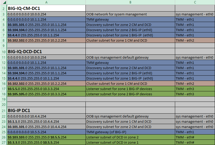
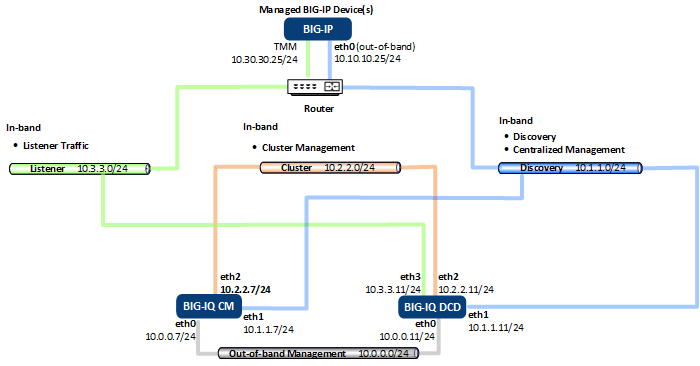
Data center 1 routing diagram and table
You can use this diagram and routing table as a visual aid as you analyze the static route requirements for a typical, four-NIC, BIG-IQ deployment. For a description of these routes, refer to To see the diagram and table for the second data center, refer to Data center 2 routing diagram and table on askf5.com.
This figure illustrates the network topology for a four subnet deployment.
This table illustrates the routing table for a four subnet deployment.
Note: The table uses a standard syntax to express a static route. The route expression is comprised by three octets: <destination address> <decimal subnet mask> <gateway>. In this expression:
- the first octet specifies the destination IP address used to communicate with the subnet the route needs to reach.
- The next octet specifies the network mask in decimal format for the subnet the route needs to reach.
- The last octet specifies the gateway for the subnet on which the route originates.