Applies To:
Show Versions
Platform Maintenance
About maintaining the platform
The VIPRION® 4800 Series platform contains several components that you can replace individually without exchanging the entire system. This platform contains these replaceable components:
- AC power supply
- DC power supply
- Fan tray
- Bezel (with LCD component)
- Blades
- Cable managers
- Chassis filter
- Power supply filter
- Annunciator cards
About AC power supplies
The VIPRION® 4800 platform supports up to four hot swappable power supplies.
The platform supports power redundancy, which ensures that the system is unaffected if a single power supply fails in a system containing more than one power supply. In the event of a power supply failure, you can replace a failed DC power supply without powering down the system. For maintenance, you can replace a working power supply, provided that there are working redundant supplies installed in the system. There must be two or more working power supplies if 1-3 blades are installed. There must be three or more working power supplies if 4-8 blades are installed. The system can operate without redundancy at max capacity with two of the four power supplies installed.
An example of an AC power supply
Installing an AC power supply
- Remove the existing supply, if one is installed.
- Loosen the captive screw on the power supply by turning it counterclockwise with a #2 Phillips screwdriver, if necessary.
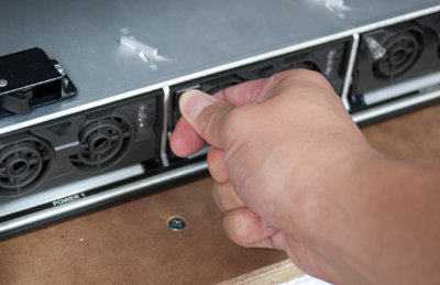
- Grasp the eject lever and pull straight toward you to eject the power supply from the chassis.
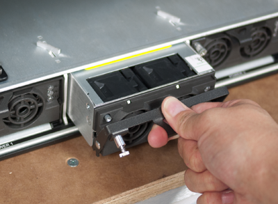
- Loosen the captive screw on the power supply by turning it counterclockwise with a #2 Phillips screwdriver, if necessary.
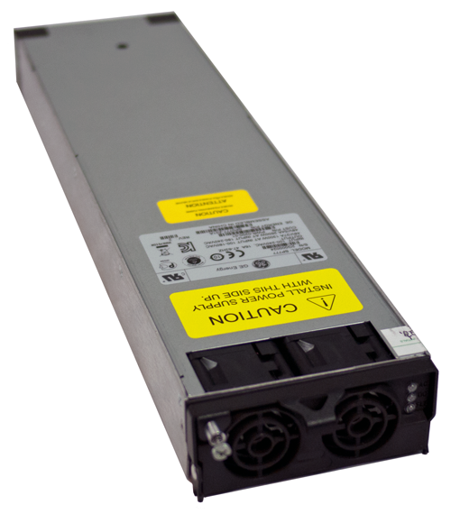
About DC power supplies
The platform supports power redundancy, which ensures that the system is unaffected if a single power supply fails in a system with a working redundant supply. For redundant operation, there must be two or more working power supplies if 1-3 blades are installed, and there must be three or more working power supplies if 4-8 blades are installed. For maintenance, you can replace a working power supply, provided that there are working redundant supplies installed in the system.
The DC power supply does not have an on/off switch. You can control the power from the rack switch or the DC power source.
VIPRION 4800 DC power supply
Installing a DC power supply
- Remove the existing supply, if one is installed.
- Loosen the captive screw on the power supply by turning it counterclockwise with a #2 Phillips screwdriver, if necessary.
- Grasp the eject lever and pull straight toward you to eject the power supply from the chassis.
- Loosen the captive screw on the power supply by turning it counterclockwise with a #2 Phillips screwdriver, if necessary.
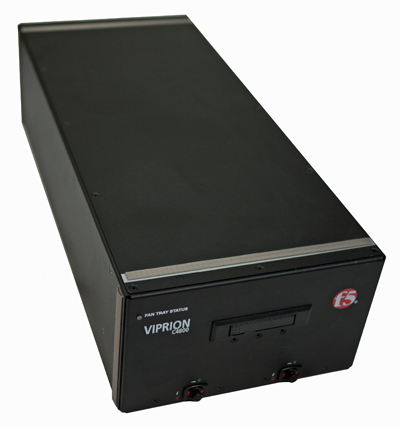
About the fan tray
The VIPRION® 4800 Series platform has a removable fan tray that is designed to maintain airflow throughout the chassis. You can change or replace the fan tray as part of the routine maintenance of the unit, or in the event of a fan failure. The fans in the fan tray run constantly while the unit is on. Over time, the fans can wear out, requiring you to replace the fan tray.
The VIPRION 4800 Series platform fan tray
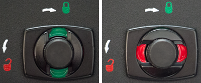
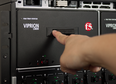
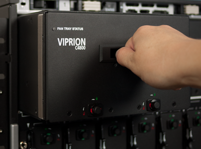
Replacing the fan tray
- Turn the compression screws on the fan tray, until the locking indicator changes color from green (locked) to red (unlocked).
- Extend the fan tray ejector handle by pressing the left side of the handle into the unit.
- Grasp the ejector handle and remove the fan tray from the chassis by pulling straight toward you.
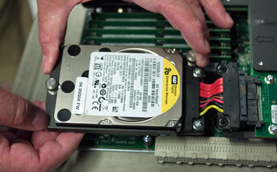
About the storage drives
By default, VIPRION® B4000 blades contain one storage drive. You can remove the drive from the blade only if your company's security requirements necessitate it when performing a Return Material Authorization (RMA) on the platform.
Replacing a storage drive assembly on a B4300 blade
- Remove the existing drive assembly, if one is installed:
- Loosen the drive assembly screws (a) by turning them counterclockwise with a Phillips screwdriver, if necessary.Note: These screws are captive and cannot be removed from the assembly.
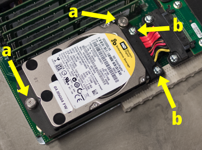
- Loosen the drive assembly screws (a) by turning them counterclockwise with a Phillips screwdriver, if necessary.
- Slide the new drive assembly into the bay and connect it to the SAS cable assembly.
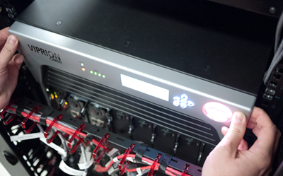
About the bezel (with LCD component)
The top bezel on the front of the VIPRION® 4800 chassis includes an LCD component that enables you to access several functions associated with the platform, such as configuring the management port for the system.
Replacing the bezel (with LCD component)
- Remove the original bezel by grasping the bezel on either side, using the indentations provided.Note: Failure to use the indentations could result in pinched fingers.
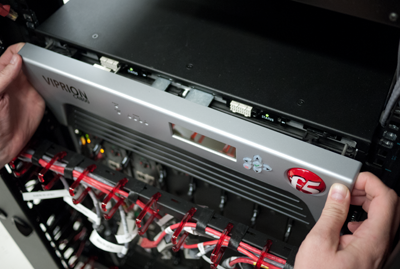
- Align the guide pins on the bezel to the corresponding holes in the chassis and push in on both sides until the bezel is secured to the chassis.
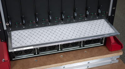
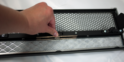
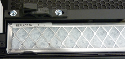
About the chassis and power supply filters
The VIPRION® 4800 platform includes replaceable chassis and power supply filters. You must remove the bottom bezel to access these filters. The chassis filter is located above the power supplies and below the blade slots. The power supply filter is located on the bottom bezel.
Replacing the chassis filter
- Pull straight out to remove the chassis filter.
Replacing the power supply filter
- Remove the power supply filter from the bezel by pressing the ejector latch.
- Insert the replacement power supply filter into the bottom bezel, with the label facing you and on the same side as the part number.
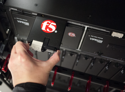
About the annunciator cards
The VIPRION® 4800 platform includes two annunciator cards. You can change or replace the cards in the event of a failure.
Replacing the annunciator cards
- Grasp both release buttons on the annunciator card, squeeze the button on the right side, and pull the old card straight out toward you.