Updated Date: 07/07/2026
Virtual Wires
To deploy a BIG-IP system without making changes to other devices on your network, you can configure the system to operate strictly at Layer 2. By deploying a virtual wire configuration, you transparently add the device to the network without having to create self IP addresses or change the configuration of other network devices that the BIG-IP device is connected to.
A virtual wire logically connects two interfaces or trunks, in any combination, to each other, enabling the BIG-IP system to forward traffic from one interface to the other, in either direction. This type of configuration is typically used for security monitoring, where the BIG-IP system inspects ingress packets without modifying them in any way.
This illustration shows a virtual wire configuration on the BIG-IP system. In this configuration, a VLAN group contains two VLANs tagged with VLAN ID 4096. Each VLAN is associated with a trunk, allowing the VLAN to accept all traffic for forwarding to the other trunk. Directly connected to a Layer 2 or 3 networking device, each interface or trunk of the virtual wire is attached to a wildcard VLAN, which accepts all ingress traffic. On receiving a packet, an interface of a virtual wire trunk forwards the frame to the other trunk and then to another network device.
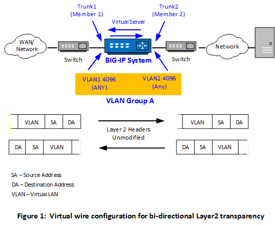
Optionally, you can create a forwarding virtual server that applies a security policy to ingress traffic before forwarding the traffic to the other trunk.
There are a few key points to remember about virtual wire configurations in general:
- An interface accepts packets in promiscuous mode, which means there is no packet modification.
- The L2 wire operates on transparent mode. The traffic is in allowed state irrespective of Global and Virtual server context default rules. To enforce any deny action on the traffic, use the explicit rules in the global context.
- The system bridges both tagged and untagged data.
- Source MAC address learning is disabled.
- Forwarding decisions are based on the ingress interface.
- Neither VLANs nor MAC addresses change.
Note: VLAN double tagging is not supported in a virtual wire configuration.
When an interface in virtual wire mode receives traffic, it first tries to associate the traffic with a VLAN defined on the virtual wire and then looks for a matching virtual server. If a virtual server is found, the forwarding action is determined by the policies configured on the virtual server.
This table describes how the BIG-IP® system handles certain conditions when the relevant interfaces are configured to use a virtual wire. The table also shows what actions you can take, if possible.
| Condition | Default Behavior | User Action |
|---|---|---|
| No VLAN for tagged traffic is found. | If the traffic is tagged but there is no VLAN for that traffic, the virtual wire dynamically creates data-path objects that enable the system to engage the forwarding path. | None. |
| No VLAN for untagged traffic is found. | Unlike for tagged traffic, where a specific VLAN is not needed, a virtual wire needs a specific VLAN to associated with untagged traffic. | Be sure to configure an untagged VLAN on the relevant virtual wire interface to enable the system to correctly handle untagged traffic. Note that many Layer 2 protocols, such as Spanning Tree Protocol (STP), employ untagged traffic in the form of BPDUs. |
| An “any” VLAN group and a VLAN configured for specific traffic exist, but there is no virtual server for the specific traffic. | A virtual wire object can include both an “any” VLAN group and a separate VLAN that’s configured to handle specific traffic. If the only virtual server you create is the one that listens for the VLAN group traffic and not specific traffic, the virtual server configured to listen for traffic on the VLAN group behaves like a wildcard virtual server. That is, the virtual server accepts all traffic for the virtual wire, including the traffic intended for the specific VLAN. | Although not a requirement, consider creating a separate virtual server to match specific traffic being forwarded. |
| No virtual server for tagged traffic is found. | If there is no matching vitual server for tagged traffic, a virtual wire forwards the traffic at Layer 2, ignoring headers at Layer 3 and above. However, even in this case the system keeps a “connection” state with a default age of 300 seconds. With a large number of TCP connections, this can cause temporary spikes in memory use. The system eventually clears these memory spikes through idle timeouts. | Create one or more virtual servers that match tagged TCP traffic on the virtual wire. Or, if unsure of the traffic types, you can create a wildcard virtual server. By creating matching or wildcard virtual servers, you can prevent such spikes in memory use. The type of virtual servers you create should be either Forwarding (IP) or Performance (Layer 4). This enables the system to close connections much faster and therefore improve system performance. Alternatively, you can configure a lower idle timeout threshold using the tmsh command sys db tm.l2forwardidletimeout <value>. |
| Layer 2 BPDU traffic. | As long as the virtual wire is able to associate the Layer 2 BPDUs to a VLAN (tagged or untagged), the system forwards all Layer 2 BPDU traffic to the peer interface. | Because many Layer 2 protocols employ untagged BPDUs, it’s a good idea to make sure you have both tagged and untagged VLANs on the virtual wire for forwarding BPDUs. |
To configure the BIG-IP system as an inline device operating in Layer 2 transparency mode, you first need to create a virtual wire configuration object. Creating a virtual wire object causes the BIG-IP system to automatically perform these actions:
- Create trunks for accepting all VLAN traffic, with Link Aggregation Protocol (LACP) enabled.
- Set the trunk members (interfaces) to virtual wire mode.
- Create two VLANs with tag 4096 that allow all Layer 2 ingress traffic.
- Create a VLAN group to logically connect the VLANs.
-
On the Main tab, click Network > Virtual Wire.
This object appears on certain BIG-IP platforms only.
The Virtual Wire screen opens.
-
Click Create.
-
In the Name field, type a name for the virtual wire object.
-
On the right side of the screen, click the double-arrow symbol to expand the Shared Objects panel.
-
Click within the Trunks heading area.
This displays a list of existing trunks, and displays the + symbol for creating a trunk.
-
Click the + symbol.
-
In the Name field, type a name for the trunk, such as
trunk_externalortrunk_internal. -
In the Interfaces list, select the check boxes for the interfaces that you want to include in the trunk.
-
From the LACP list, select Enabled.
This enables the Link Aggregation Control Protocol (LACP) to monitor link availability within the trunk.
-
Click Commit.
If you do not see the Commit button, try using a different browser.
This creates the trunk that you can specify as an interface when you complete the creation of the virtual wire object.
-
Repeat steps 6 through 10 to create a second trunk.
-
In the Member 1 column, from the Interfaces/Trunks list, select a trunk name, such as
trunk_external. -
In the Member 2 column, from the Interfaces/Trunks list, select another trunk name, such as
trunk_internal. -
In the VLAN Traffic Management Configuration column, for the Define VLANs list, use the default value of No.
-
Click Done Editing.
-
Click Commit Changes to System.
After you perform this task, the BIG-IP system contains a virtual wire object, two trunks, two VLANs, and a VLAN group.