Updated Date: 07/07/2026
Managing Network Objects
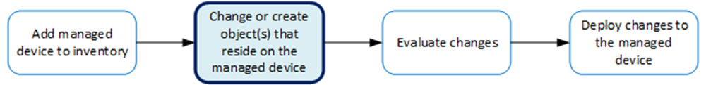
The workflows for creating a new object, or for changing the settings for objects that already reside on a managed device, are very similar. In each case, there are four tasks to perform.
This figure illustrates the workflow to manage the objects on BIG-IP devices. Changing the settings or creating the object is the second step in this process.
You can make revisions to the configuration of Local Traffic objects to simplify managing your devices.
-
At the top of the screen, click Configuration, then, on the left, click NETWORK.
-
Under NETWORK, click the object type that you want to modify, such as Interfaces or VLANs.
The screen displays a list of objects of that type that are defined on this BIG-IQ.
-
Click the name of the object you want to change.
The Properties screen for the selected object opens.
-
Make changes to the properties that you want to modify.
-
When you are satisfied with the changes you have made, click Save & Close.
The revisions you saved are made, and the Properties screen for the selected object closes.
Changes that you make are made only to the pending version. The pending version serves as a repository for changes you stage before deploying them to the managed device. Object settings for the pending version are not the same as the object settings on the actual BIG-IP device until they are deployed or discarded.
To apply the pending version settings to the BIG-IP device, you next need to deploy the revisions.
You can use the BIG-IQ Local Traffic component to enable or disable network interfaces on a managed device.
Important: When you revise configurations on devices that belong to a high availability cluster, it is important to let the changes synchronize to the cluster members instead of trying to make the same changes to multiple devices. If you try to replicate changes you made on one device in the cluster, the next config sync attempt could fail.
-
At the top of the screen, click Configuration, then, on the left, click NETWORK > Interfaces.
The screen displays the list of interfaces defined on this device.
Note: If you select the check box for an interface, you can either enable or disable it. You can also view details about other configuration objects to which this interface relates.
-
Select the check box for the interface you want to change, and then click Enable or Disable.
The State for the selected interface changes on the BIG-IQ.
Changes that you make are made only to the pending version. The pending version serves as a repository for changes you stage before deploying them to the managed device. Object settings for the pending version are not the same as the object settings on the actual BIG-IP device until they are deployed or discarded.
When you finish revising the settings for this interface, you need to evaluate and then deploy the changes to the target device. Until you deploy the changes stored in the pending version, objects on the managed device are not changed.
You can use the BIG-IQ Local Traffic component to add a route to a managed device so you can better control the application traffic on that device.
Important: When revising configurations on devices that belong to a high availability cluster, it is important to let the changes synchronize to the cluster members instead of trying to make the same changes to multiple devices. If you try to replicate changes you made on one device in the cluster, the next config sync attempt could fail.
-
At the top of the screen, click Configuration, then, on the left, click NETWORK > Routes.
The screen displays the list of routes defined on this device.
Note: If you select the check box for a route, you can delete it. You can also view details about other configuration objects to which this route relates.
-
Click Create.
The New Route screen opens.
-
Type a Name for the route you are creating.
Note: For detailed information on the impact of using a particular route parameter value, refer to the BIG-IP TMOS: Routing Administration on support.F5.com.
-
If the device for which you are creating this route is in a silo as part of a conflict resolution work flow, select that Silo here; otherwise, leave the default setting.
Note: For detailed work flows explaining how you can use a silo to resolve configuration object conflicts, refer to BIG-IQ: Resolving Device Object Conflicts on support.f5.com.
-
Type in a brief Description for the route you are creating.
-
Select the Device on which to create the route.
-
For Partition, type the name of the BIG-IP device partition on which you want to create the route.
Note: In the AS3 user interface, the BIG-IP device partition to which services deploy is referred to as the tenant. Do not deploy any objects to a partition that has been used to deploy AS3 application services using the Configuration tab. For additional detail about partitions and tenants, refer to AS3 tenant name details in the Managing BIG-IQ AS3 templates article on support.f5.com
-
In the Destination/Mask field, type a self IP address and netmask for this route.
These addresses display in the Destination and Netmask columns of the routing table.
For example:
10.145.193.0/24 -
Specify the Resource setting.
- To use a gateway, select Use Gateway, and then from Gateway Address, choose either IP Address or IPv6 Link-Local Address. This is the method through which you want the BIG-IQ system to forward packets to the route destination.
- To use a pool, select Use Pool, and then select the pool through which you want the BIG-IQ system to forward packets to the route destination.
- To use a VLAN or tunnel, select Use VLAN/Tunnel, and then select the VLAN or tunnel through which you want the BIG-IQ system to forward packets to the route destination.
- To reject packets forwarded to the route destination, select Reject.
-
In the MTU field, type an optional frame size value for Path Maximum Transmission Unit (MTU).
By default, BIG-IP devices use the standard Ethernet frame size of 1518 bytes (1522 bytes if VLAN tagging is used) with the corresponding MTU of 1500 bytes. For BIG-IP devices that support Jumbo Frames, you can specify another MTU value.
-
Click Save & Close.
The system creates the new route with the settings you specified.
Changes that you make are made only to the pending version. The pending version serves as a repository for changes you stage before deploying them to the managed device. Object settings for the pending version are not the same as the object settings on the actual BIG-IP device until they are deployed or discarded.
When you finish specifying the settings for this route, you need to evaluate and then deploy the changes to the target device. Until you deploy the changes stored in the pending version, objects on the managed device are not changed.
You can use the BIG-IQ Local Traffic component to add a self IP address to a managed device. You can then associate that self IP address with a VLAN, to access hosts in that VLAN.
Important: When revising configurations on devices that belong to a high availability cluster, it is important to let the changes synchronize to the cluster members instead of trying to make the same changes to multiple devices. If you try to replicate changes you made on one device in the cluster, the next config sync attempt could fail.
-
At the top of the screen, click Configuration, then, on the left, click NETWORK > Self IPs.
The screen displays the list of self IP addresses defined on this device.
Note: If you select the check box for a self IP, you can delete it. You can also view details about other configuration objects to which this self IP relates.
-
Click Create.
The New Self IP screen opens.
-
Type a Name for the self IP address you are creating.
Note: For detailed information on the impact of using a particular self IP parameter value, refer to the Self IP Addresses chapter in the BIG-IP TMOS: Routing Administration guide on support.F5.com.
-
If the device for which you are creating this self IP address is in a silo as part of a conflict resolution work flow, select that Silo here; otherwise, leave the default setting.
Note: For detailed work flows explaining how you can use a silo to resolve configuration object conflicts, refer to BIG-IQ: Resolving Device Object Conflicts on support.f5.com.
-
Select the Device on which to create the self IP address.
-
For Partition, type the name of the BIG-IP device partition on which you want to create the self IP.
Note: In the AS3 user interface, the BIG-IP device partition to which services deploy is referred to as the tenant. Do not deploy any objects to a partition that has been used to deploy AS3 application services using the Configuration tab. For additional detail about partitions and tenants, refer to AS3 tenant name details in the Managing BIG-IQ AS3 templates article on support.f5.com
-
In the IP Address field, type either an IPv4 or an IPv6 address.
For an IPv4 address, you should specify a /32 IP address per RFC 3021.
-
In the Netmask field, type the netmask for this self IP address. You must type the full netmask.
Specifying the prefix length in bits is not supported. For example, you could type 255.255.255.255 or ffff:ffff:ffff:ffff:0000:0000:0000:0000 or ffff:ffff:ffff:ffff:: (with two colons at the end).
-
For VLAN /Tunnel, select the VLAN or tunnel to associate with this self IP address.
Important: When you assign a VLAN to this self IP address, keep in mind that the self IP address and VLAN must use the same route domain. For example, if you assign self IP 10.0.0.0%20 (route domain with ID 20) to VLAN-1, you will not be able to assign VLAN-1 to any route domain except a route domain with ID 20.
-
Specify the Port Lockdown.
- Select Allow Default to activate only the default protocols and services. You can determine the supported protocols and services by logging in to the target BIG-IP device and running tmsh list net self-allow defaults on the command line.
- Select Allow All to activate all TCP and UDP services on this self IP address.
- Select Allow None to specify that this self IP address accepts no traffic. If you are using this self IP address as the local endpoint for WAN optimization, select this option to avoid potential port conflicts.
- Select Allow Custom or Allow Custom (Include Default) to expand the Custom List setting, where you can specify the ports, protocols, and services to activate on this self IP address.
-
Select a specific Traffic Group for the self IP address.
-
Click Save & Close.
The system creates the new self IP address with the settings you specified.
Changes that you make are made only to the pending version. The pending version serves as a repository for changes you stage before deploying them to the managed device. Object settings for the pending version are not the same as the object settings on the actual BIG-IP device until they are deployed or discarded.
When you finish specifying the settings for this self IP address, you need to evaluate and then deploy the changes to the target device. Until you deploy the changes stored in the pending version, objects on the managed device are not changed.
Use this procedure to create a new trunk on a managed BIG-IP device.
-
On the Main tab, click Network > Trunks.
The Trunks screen opens.
-
Click Create.
The New Trunk screen opens.
-
In the Name field, type in a unique name for the trunk you are creating.
-
If the device for which you are creating this trunk is in a silo as part of a conflict resolution work flow, select that Silo here; otherwise, leave the default setting.
Note: For detailed work flows explaining how you can use a silo to resolve configuration object conflicts, refer to BIG-IQ: Resolving Device Object Conflicts on support.f5.com.
-
From the Device list, select the device on which to create the trunk.
-
For Partition, type the name of the BIG-IP device partition on which you want to create the new trunk.
Note: In the AS3 user interface, the BIG-IP device partition to which services deploy is referred to as the tenant. Do not deploy any objects to a partition that has been used to deploy AS3 application services using the Configuration tab. For additional detail about partitions and tenants, refer to AS3 tenant name details in the Managing BIG-IQ AS3 templates article on support.f5.com
-
Use the Move buttons (> and >) to control which Interfaces this trunk uses.
-
From Link Select Policy, select the policy that this trunk uses to determine which member link (interface) handles new traffic.
-
From Distribution Hash, select the basis for the hash that the system uses as the frame distribution algorithm. The system uses the resulting hash to determine which interface to use for forwarding traffic.
-
Click Save & Close.
The system creates the new trunk with the settings you specified.
After you perform these steps, each BIG-IP system configuration contains a VLAN of the same name that you can assign to an IPv6 self IP address.
You can use the BIG-IQ Local Traffic component to add a route domain to a managed device. Using route domains, you can assign the same IP address to more than one device on a network, as long as each instance of the IP address resides in a separate route domain.
-
At the top of the screen, click Configuration, then, on the left, click NETWORK > Route Domains.
The screen displays the list of route domains defined on this device.
-
Click Create.
The New Route Domain screen opens.
-
In the Name field, type in a unique name for the route you are creating.
-
If the device for which you are creating this route domain is in a silo as part of a conflict resolution work flow, select that Silo here; otherwise, leave the default setting.
Note: For detailed work flows explaining how you can use a silo to resolve configuration object conflicts, refer to BIG-IQ: Resolving Device Object Conflicts on support.f5.com.
-
In the ID field, type an integer to represent the route domain.
The integer must be unique on the BIG-IP device and be between 1 and 65534. The default value (0) indicates that all VLANs on a system pertain to this route domain. When you create new route domains, you can assign VLANs to those route domains which moves the VLANs out of the default route domain.
Important: When you assign a VLAN to a route domain, keep in mind that any self IP addresses that use that VLAN must use the same route domain. For example, if self IP 10.0.0.0%20 (route domain with ID 20) is assigned to VLAN-1, you cannot assign VLAN-1 to any route domain except a route domain with ID 20.
-
In the Description field, type in a brief description for the route domain you are creating.
-
From the Device list, select the device on which to create the route domain.
-
For Partition, type the name of the BIG-IP device partition on which you want to create the route domain.
Note: In the AS3 user interface, the BIG-IP device partition to which services deploy is referred to as the tenant. Do not deploy any objects to a partition that has been used to deploy AS3 application services using the Configuration tab. For additional detail about partitions and tenants, refer to AS3 tenant name details in the Managing BIG-IQ AS3 templates article on support.f5.com
-
Select Strict Isolation if you want to enforce cross-routing restrictions.
When Enabled is selected, routes cannot cross route domain boundaries (so they are strictly isolated to the current route domain). The default is enabled. When this setting is disabled, routes can cross route domains. For example, you could add a route to the routing table with a 10.0.0.0%20 (route domain 20) destination and a gateway of 172.27.84.29%32 (route domain 32).
-
To specify a VLAN or tunnel for the BIG-IP device to use in the route domain, select it in the Available list, and use the arrow to add it to the Selected list.
Note: A VLAN and tunnel can only be referenced by one route domain at a time, so if the VLAN or tunnel you select is currently referenced by another route domain, it will be removed from that route domain when you attach it to this route domain.
Note: Before removing a VLAN from a route domain, recall that every self IP address must use the same route domain as its VLAN, so make sure the VLAN is not already in use by a self IP address. For example, if a self IP address uses a VLAN named VLAN-2 and also uses the default route domain 0, do not remove VLAN-2 from route domain 0.
-
Click Save & Close.
The system creates the new route domain with the settings you specified.
Changes that you make are made only to the pending version. The pending version serves as a repository for changes you stage before deploying them to the managed device. Object settings for the pending version are not the same as the object settings on the actual BIG-IP device until they are deployed or discarded.
When you finish revising the settings for this route domain, the next step is to evaluate and then deploy the changes to the target device. Until you deploy the changes stored in the pending version, objects on the managed device are not changed.
You can use the BIG-IQ Local Traffic component to add a VLAN to a managed device. Using VLANs, you can assign the same IP address to more than one device on a network, as long as each instance of the IP address resides in a separate VLAN.
-
At the top of the screen, click Configuration, then, on the left, click NETWORK > VLANs.
The screen displays the list of VLANs defined on this device.
-
Click Create.
The New VLAN screen opens.
-
Type a unique Name for the VLAN you are creating.
Note: For detailed information on the impact of using a particular VLAN parameter value, refer to the VLANs VLAN Groups and VXLAN chapter in the BIG-IP TMOS: Routing Administration guide on support.F5.com.
-
If the device for which you are creating this VLAN is in a silo as part of a conflict resolution work flow, select that Silo here; otherwise, leave the default setting.
Note: For detailed work flows explaining how you can use a silo to resolve configuration object conflicts, refer to BIG-IQ: Resolving Device Object Conflicts on support.f5.com.
-
Type a brief Description for the VLAN you are creating.
-
Type a Tag number for the VLAN.
The tag number can be between 1 and 4094, but must be unique on the target device. If you do not specify a value, the system automatically assigns a tag number.
-
Select the Device on which to create the VLAN.
-
For Partition, type the name of the BIG-IP device partition on which you want to create the VLAN.
-
In the MTU field, specify the maximum transmission unit (MTU) for traffic on this VLAN.
The default is 1500.
-
To specify which interfaces this VLAN uses for traffic management, select one from the Interface list, and then select the Tagging for it.
You can add more than one interface by clicking the Add + button.
-
For the Hardware SYN Cookie Protection setting, select or clear the check box.
When you enable this setting, the BIG-IP system triggers hardware SYN cookie protection for this VLAN.
Enabling this setting causes additional settings to appear. These settings appear on specific BIG-IP platforms only.
-
For the Syncache Threshold setting, retain the default value or change it to suit your needs.
The Syncache Threshold value represents the number of outstanding SYN flood packets on the VLAN that will trigger the hardware SYN cookie protection feature.
When the Hardware SYN Cookie setting is enabled, the BIG-IP system triggers SYN cookie protection in either of these cases, whichever occurs first:
- The number of TCP half-open connections defined in the LTM setting Global SYN Check Threshold is reached.
- The number of SYN flood packets defined in this Syncache Threshold setting is reached.
-
For the SYN Flood Rate Limit setting, retain the default value or change it to suit your needs.
The SYN Flood Rate Limit value represents the maximum number of SYN flood packets per second received on this VLAN before the BIG-IP system triggers hardware SYN cookie protection for the VLAN.
-
For Auto Last Hop select whether you want to designate the VLAN as the last hop for TMM traffic.
-
For CMP Hash select the traffic disaggregation criteria to use for this VLAN.
The default value uses TCP/UDP source/destination ports.
-
For DAG Tunnel select how you want this VLAN to enable hardware-based disaggregation.
This setting determines how the disaggregator (DAG) processes received packets that are encapsulated using one of the supported tunneling protocols (such as, NVGRE, VXLAN, EtherIP, or IPIP). There are two options for DAG tunnel:
- Inner disaggregates encapsulated packets based on the inner headers. Using the inner headers typically provides more information to the DAG which allows for a better distribution of packets across TMM instances. If you select a value of Inner, you must also configure a bigdb variable to specify a port number before any associated tunnels can use the inner headers.
- Outer uses the outer headers of encapsulated packets without inspecting the inner headers. This is the default value.
-
For DAG Round Robin select how yo uwant this VLAN to prevent stateless traffic from overloading a few TMM instances, a condition that can disable an entire BIG-IP system.
When enabled, this setting causes the BIG-IP system to load balance the traffic among TMMs evenly, instead of using a static hash. Stateless traffic in this case includes non-IP Layer 2 traffic, ICMP, some UDP protocols, and so on. This setting is disabled by default.
This feature is particularly useful for firewall and Domain Name System (DNS) traffic. For example, this feature prevents certain types of DDoS attacks, such as an ICMP DDoS attack that can overload the system by sending the same packets repeatedly to a specific subset of TMMs.
The disaggregation of traffic occurs only to TMMs that are local to a given high-speed bridge (HSB).
-
For Fail-safe, select whether you want this BIG-IP to base redundant-system failover on VLAN-related events.
When you enable this setting, BIG-IQ displays two additional controls.
-
For Fail-safe Timeout, type the number of seconds you want the system to wait before failing.
-
For Action, select the action that you want the BIG-IP to perform when the timeout period expires
-
-
If you want the BIG-IP to verify that the return path for an initial packet is through the same VLAN from which the packet originated, then for Source Check, select the Enabled check box.
Note: The system only enables source checking if the global setting Auto Last Hop is disabled.
-
Specify the sFlow polling interval and sampling rate for this VLAN.
-
For the Polling interval, either select default, or select Specify and type the number of seconds you want between each sFlow poll.
The default interval between sFlow polls is 10 seconds.
-
For the Sampling Rate, either select default, or select Specify and type the ratio of sFlow samples to observed packets.
The default sampling rate is 2048, which means that the system randomly generates 1 sample for every 2048 packets observed.
-
-
Click Save & Close.
The system creates the new VLAN with the settings you specified.
Changes that you make are made only to the pending version. The pending version serves as a repository for changes you stage before deploying them to the managed device. Object settings for the pending version are not the same as the object settings on the actual BIG-IP device until they are deployed or discarded.
When you finish specifying the settings for this VLAN, you need to evaluate and then deploy the changes to the target device. Until you deploy the changes stored in the pending version, objects on the managed device are not changed.
Use this procedure to create a VLAN Group on your managed BIG-IP system in your configuration.
-
On the Main tab, click Network > VLAN Groups.
The VLAN Groups screen opens.
-
Click Create.
The New VLAN screen opens.
-
Type a unique Name for the VLAN group you are creating.
-
If the device for which you are creating this VLAN group is in a silo as part of a conflict resolution work flow, select that Silo here; otherwise, leave the default setting.
Note: For detailed work flows explaining how you can use a silo to resolve configuration object conflicts, refer to BIG-IQ: Resolving Device Object Conflicts on support.f5.com.
-
From the Device list, select the device on which to create the VLAN group.
BIG-IQ lists the VLANs and tunnels that reside on the device you selected.
-
Add the VLANs and tunnels you want to this group, then configure the remaining settings needed to suit the requirements for this VLAN group depending on how you plan to use it.
-
Click Save & Close.
-
Click Finished.
The screen refreshes, and it displays the new VLAN Group in the list.
After you perform these steps, each BIG-IP system configuration contains a VLAN of the same name that you can assign to an IPv6 self IP address.
You can use the BIG-IQ to add a DNS resolver to a managed device. Using DNS resolvers, you can assign the same IP address to more than one device on a network, as long as each instance of the IP address resides in a separate DNS resolver. When the BIG-IP system receives a query that cannot be resolved from the cache, the system forwards the query to a nameserver associated with the matching forward zone. When the nameserver returns a response, the BIG-IP system caches the response, and returns the response to the resolver making the query.
-
At the top of the screen, click Configuration, then, on the left, click NETWORK > DNS Resolvers.
The screen displays the list of DNS resolvers defined on this device.
Note: If you select the check box for a DNS resolver, you can delete it. You can also view details about other configuration objects to which this DNS resolver relates.
-
Click Create.
The New DNS Resolver screen opens.
-
Type a unique Name for the DNS resolver you are creating.
-
If the device for which you are creating this DNS resolver is in a silo as part of a conflict resolution work flow, select that Silo here; otherwise, leave the default setting.
Note: For detailed work flows explaining how you can use a silo to resolve configuration object conflicts, refer to BIG-IQ: Resolving Device Object Conflicts on support.f5.com.
-
For Partition, type the name of the BIG-IP device partition on which you want to create the DNS resolver.
Note: In the AS3 user interface, the BIG-IP device partition to which services deploy is referred to as the tenant. Do not deploy any objects to a partition that has been used to deploy AS3 application services using the Configuration tab. For additional detail about partitions and tenants, refer to AS3 tenant name details in the Managing BIG-IQ AS3 templates article on support.f5.com
-
Select the Route Domain Name that this resolver uses for outbound traffic.
-
To specify the Resolver properties, expand the Resolver area.
-
For the Cache Size, type the size of the internal DNS resolver cache.
The default is 5767168 bytes. After the cache reaches this size, when new or refreshed content arrives, the system removes expired and older content and caches the new or updated content.
-
Select Answer Default Zones if you want the system to answer DNS queries for the default zones localhost, reverse, 127.0.0.1, ::1, and AS112.
The default is disabled, meaning that the system passes along the DNS queries for the default zones.
-
Select Randomize Query Character Case if you want the internal DNS resolver to randomize character case in domain name queries issued to the root DNS servers.
-
To specify the Traffic properties, expand the Traffic area and select the format or formats for which you want the system to answer and issue queries.
-
To specify a forward zone used to resolve matching DNS queries, expand the Forward Zones area and click Add.
A popup screen opens.
-
Type in a unique Name for the forward zone you are creating.
-
Type an IP Address for the forward zone you are creating.
-
In the Service Port field, type in the port number for the forward zone you are creating.
-
Click the Add button next to the Service Port.
The address and port combination is added to the Nameservers box.
-
To add additional nameservers, repeat the last two sub-steps.
-
-
When you are satisfied with the new forward zone, click the Add button.
The popup screen closes and BIG-IQ adds the new zone.
-
If you have specified forward zones, select the check boxes for the zones you want to use.
-
When you are satisfied with the new DNS resolver, click Save & Close.
The system creates the new DNS resolver with the settings you specified.
Changes that you make are made only to the pending version. The pending version serves as a repository for changes you stage before deploying them to the managed device. Object settings for the pending version are not the same as the object settings on the actual BIG-IP device until they are deployed or discarded.
To pin this resolver to specific devices, click Configuration > LOCAL TRAFFIC > Pinning Policies.
Note: For detail about how pinning works, refer to Managing Object Pinning on support.f5.com.
When you finish revising the settings for this DNS resolver, you need to evaluate and then deploy the changes to the target device. Until you deploy the changes stored in the pending version, objects on the managed device are not changed.
You can use the BIG-IQ to add a tunnel to a managed device.
Note: The tunnel Name, Device, and Tunnel Profile Reference are the only required properties when you create a tunnel. You can leave the remaining properties on this screen unchanged. These properties perform the same function as they do when you configure a tunnel on a BIG-IP device.
-
At the top of the screen, click Configuration, then, on the left, click NETWORK > Tunnels.
The screen displays the list of tunnels defined on this device.
-
Click Create.
The New Tunnel screen opens.
-
Type a Name for this tunnel.
-
If the device for which you are creating this tunnel is in a silo as part of a conflict resolution work flow, select that Silo here; otherwise, leave the default setting.
Note: For detailed work flows explaining how you can use a silo to resolve configuration object conflicts, refer to BIG-IQ: Resolving Device Object Conflicts on support.f5.com.
-
From the Device list, select the device on which you want to create this tunnel.
-
Select the Tunnel Profile Reference from the list of tunnel profiles that reside on the device on which you are creating the tunnel.
Additional fields display based on the profile you selected. These fields perform just as they do when you configure a tunnel on a BIG-IP. For details on what each field is used for and how the settings do refer to the BIG-IP documentation on support.f5.com.
-
Click Save & Close.
The system creates the new tunnel with the settings you specified.
Changes that you make are made only to the pending version. The pending version serves as a repository for changes you stage before deploying them to the managed device. Object settings for the pending version are not the same as the object settings on the actual BIG-IP device until they are deployed or discarded.
When you finish revising the settings for this tunnel, the next step is to evaluate and then deploy the changes to the target device. Until you deploy the changes stored in the pending version, objects on the managed device are not changed.
You can use the BIG-IQ to add a tunnel profile to a managed device.
Note: The profile Name, Type, and Parent Profile are the only required properties when you create a tunnel profile. You can leave the remaining properties on this screen unchanged. These properties perform the same function as they do when you configure a profile on a BIG-IP device.
-
At the top of the screen, click Configuration, then, on the left, click NETWORK > Tunnel Profiles.
The screen displays the list of tunnel profiles defined on this device.
-
Click Create.
The New Tunnel Profile screen opens.
-
Type a Name for this profile.
-
If the device for which you are creating this tunnel is in a silo as part of a conflict resolution work flow, select that Silo here; otherwise, leave the default setting.
Note: For detailed work flows explaining how you can use a silo to resolve configuration object conflicts, refer to BIG-IQ: Resolving Device Object Conflicts on support.f5.com.
-
Select the Type of the tunnel profile you want to create.
The Parent Profile setting displays the list of parent profiles that match your selection.
-
From Parent Profile, select the parent profile from which you want your profile to inherit settings.
A number of additional settings display, specifying the parameters associated with the parent profile you selected. There are two controls for each setting.
- A check box controls whether you want to override the inherited value for that field.
- A second control (type varies by field) sets the value you want for the parameter.
-
For any settings you want to override, select the check box and then specify the value you want for the fields you selected.
Note: You can select Override All if you want to override all of the parent profile property values.
Important: When you override a parent profile property, future changes you make to this profile property in the parent profile will not be inherited by this child profile. So, selecting Override All effectively disconnects this profile from its parent.
-
Click Save & Close.
The system creates the new tunnel profile with the settings you specified. You can now attach this tunnel profile to a virtual server or use it as the Tunnel Profile Reference when you create a new tunnel.
-
To pin this profile to specific devices, click Configuration > LOCAL TRAFFIC > Pinning Policies.
Note: For detail about how pinning works, refer to Managing Object Pinning on support.f5.com.
Changes that you make are made only to the pending version. The pending version serves as a repository for changes you stage before deploying them to the managed device. Object settings for the pending version are not the same as the object settings on the actual BIG-IP device until they are deployed or discarded.
When you finish revising the settings for this tunnel, the next step is to evaluate and then deploy the changes to the target device. Until you deploy the changes stored in the pending version, objects on the managed device are not changed.