Updated Date: 07/07/2026
Platform Installation
After you have reviewed the hardware requirements and become familiar with the r5000/r10000/r12000 Series platform, you can install the unit into a 19-inch rack.
Warning: Due to the weight of the platform, at least two people are required to install this chassis into a rack. Failing to use two people can result in severe personal injury or equipment damage.
Important: Before you install this platform, review the environmental guidelines to make sure that you are installing the platform into a compatible rack and in the appropriate environment.
Note: F5 recommends that you keep all original packaging, in case you need to repackage and ship the platform later.
You use the quick-install rails to install into square hole, round hole, or threaded hole cabinets, using the screws provided.
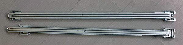
For information about installing the platform using the quick-install rails, see the instruction guide provided by the manufacturer, which is included with the rail hardware.
After installing the platform, secure the chassis to the rack with the rail lock brackets that are provided.
When you are installing with the quick-install rail kit, use these components.
| Quantity | Hardware |
|---|---|
| 2 | Quick-install rails |
| 4 | #8-32 truss head screws (from rail kit) |
| 2 | Flat washers (from rail kit) |
| 4 | M3 x 8mm flathead screws, black with patch (threadlock) (for rail lock brackets) |
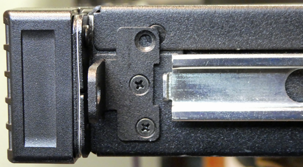
Be sure that the rails are installed onto the chassis before you install the rail lock brackets.
The rail lock brackets secure the platform to the rack when you are using the quick-install rail kit.
-
Use a #1 Phillips screwdriver to attach the rail lock brackets to each side of the unit using two of the black M3 x 8mm flathead screws that are provided with the platform.
Use 5 inch-pounds (0.6 Newton-meters) of torque on these screws.
-
Slide the unit into the rack.
Warning: Due to the weight of the platform, at least two people are required to install this chassis into a rack. Failing to use two people can result in severe personal injury or equipment damage.
-
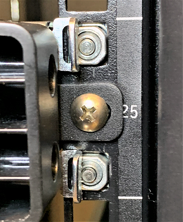
Use a #2 Phillips screwdriver to secure the rail lock brackets to the rack on each side of the unit using one of the #8-32 truss head screws that are provided with the platform.
Use 14 to 16 inch-pounds (1.6 to 1.8 Newton-meters) of torque on these screws.
Note: For square hole racks, use one screw and washer from the quick-install rail kit hardware to secure the rail to the rear end of the rack.
If you are installing the platform into a 19-inch two-post (telco-style) rack, you use the mid-mount brackets. For installing the platform into all other types of racks or cabinets, you should use the quick-install rail kit.
When you are installing with the mid-mount bracket kit, use these components.
| Quantity | Hardware |
|---|---|
| 2 | Mid-mounting brackets |
| 6 | M3 x 8mm flathead screws, black with patch |
Review the environmental guidelines to make sure that you are installing and using the platform in the appropriate environment.
Warning: Due to the weight of the platform, at least two people are required to unpack and install it. Failing to use two people can result in severe personal injury or equipment damage and might violate safety regulations.
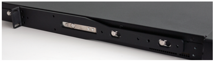
This platform includes mid-mount brackets that you can use to attach the unit directly to a 19-inch two-post (telco-style) rack.
-
Align the holes on the mid-mount bracket with the hardware on the side of the unit, and slide the bracket forward to secure it into place.
-
Secure the bracket to the unit using three of the M3 x 8mm flathead screws that are provided with the kit. Use 4 to 6 inch-pounds (.5 to .7 Newton-meters) of torque on these screws.
-
Repeat steps 1 and 2 for the other bracket.
-
Lift the unit into place in the rack.
Warning: Due to the weight of the appliance, this step requires two people.
-
Secure the unit to the rack using appropriate rack mount screws for the rack on each side. The unit must be fastened securely to the rack to provide adequate stability and to prevent the unit from falling out of the rack.
You must ground the platform after you install it in a rack. The chassis ground lug is located on the back of the platform.
Do not secure multiple bonding or grounding connectors with the same bolt. The grounding connectors do not need to be removed to perform service or installation procedures. You can connect other bonding or grounding conductors to a grounding connector provided a reliable bond between the connector and the equipment is not disturbed during installation, service, or maintenance of the platform.
Important: All grounding cable terminal lugs must meet appropriate safety standards.
Note: The platform must be grounded to a common bonding network (CBN).
You must provide these components to properly ground the chassis:
- Crimping tool
- Single ring ground terminal lug
- One 6 AWG copper wire long enough to reach from the chassis to the common bonding network (CBN)
After the unit is installed in the rack and before you provide power to the system, you need to connect the grounding hardware.
-
Remove the M5 Keps nuts from the ground lug on the back of the chassis.
-
Attach a ground ring terminal to the 6 AWG copper ground wire.
-
Install the ground ring terminal onto the chassis ground terminal.
-
Secure the ground ring terminal with the M5 Keps nuts.
Use 18 to 24 inch-pounds (2.0 to 2.7 Newton-meters) of torque on these Keps nuts.
-
Connect the ground wire to a common bonding network (CBN).
After you have installed the unit into the rack, connect the cables and other hardware.
Important: In the event that network access is impaired or not yet configured, the serial console might be the only way to access the unit. You should perform all installations and upgrades using the serial console, as these procedures require reboots, in which network connectivity is lost temporarily.
-
If you are using the default network configured on the management interface, connect an Ethernet cable to the management port.
Note: For EMI compliance, shielded cables are required for the management port, and the shield must be grounded at both ends.
-
Connect the console port to a serial console server. Depending on which system you have and the console network to which you are attaching, you can use either the supplied RJ45 to DB9 console port cable or the RJ45F to RJ45M rolled serial adapter to connect the system to a serial console.
-
Connect the RJ45 to DB9 console port cable to the console port on the system.
Note: The default baud rate and serial port configuration is 19200/8-N-1.
-
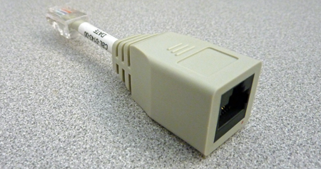
Connect the RJ45F to RJ45M rolled serial adapter to the console port if you are connecting the system to a serial console server with a standard CAT5 cable, and then connect the CAT5 cable to the adapter. The adapter provides the appropriate pinout connection to your equipment. For information about cable and connector pinout specifications, see F5 Platforms: Accessories.
-
-
Connect power to installed power supply units (PSUs):
Note: Be sure to route the power cords away from the fan tray so that the cords do not impede access to it.
-
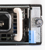
For AC-powered systems, connect an auto-locking power cable to the power input panel on all installed PSUs, and then connect the cable to the power source.
Note: Not all country-specific power cables include a locking feature.
Note: To remove the locking power cord, pull one or both of the power cord locking tabs away from the power supply.
-
For HVDC-powered systems, connect an auto-locking power cable to the power input panel on all installed PSUs, and then connect the cable to the power source.
Note: Not all country-specific power cables include a locking feature.
Note: To remove the locking power cord, pull one or both of the power cord locking tabs away from the power supply.
-
For DC-powered systems, attach an assembled DC terminal block to all installed PSUs, and then connect the cables to your DC mains power source.
-
-
Connect any optical transceiver modules.
Important: Use only IEC/EN 60825-1 Class I SFP modules, and for safety ensure not to look directly into fiber cable ends.
-
Remove the protective film from the LCD touchscreen using the small cutout on the lower right corner of the film.
You can now assign a management IP address to the system and license the system.
Optionally, you should run the QKView utility. This utility collects configuration and diagnostic information about your system into a single file that you can provide to F5 Technical Support to aid in troubleshooting. For more information, see F5 rSeries Systems: Supportability.
You can manage an F5 rSeries platform by connecting to the system using the management IP address. The system supports configuring management addresses either manually or using DHCP and in both IPv4 and IPv6 formats.
You can manage your system using these methods:
- CLI
- webUI
- Rest API
For information about initial software configuration of your system, see F5 rSeries Systems: Getting Started.