Updated Date: 07/07/2026
Platform Maintenance
The VELOS platform contains several components that you can replace individually without exchanging the entire system. This platform contains these replaceable components:
- System controller
- Front bezel (with LCD touchscreen)
- AC power supply unit (PSU)
- DC power supply unit
- PSU controller
- Fan tray
The VELOS platform supports system controller redundancy, which ensures that the system continues to operate if a single system controller fails in a system with two working controllers installed. As long as there is a working system controller installed in the system, you can change or replace the other system controller as part of the routine maintenance of the unit, or in the event of a system controller failure.
| Chassis | System Controller | Total slots | Rack units (RU) |
|---|---|---|---|
| CX410 | SX410 | 4 | 4 |
| CX1610 | SX410 | 8 | 16 |
Important: This product is sensitive to electrostatic discharge (ESD). F5 recommends that you use proper ESD grounding procedures and equipment when you install or maintain the unit, including attaching a ground strap to the ground strap receptacle location on the front left side of the chassis.
You can change or replace a system controller in a VELOS chassis as part of the routine maintenance of the unit or in the event of a hardware failure.
Note: All photos shown are examples. The appearance of your components or accessories might vary slightly.
-
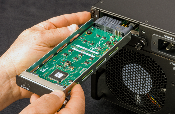
Identify the system controller that you would like to remove from the chassis.
The chassis supports system controller hot swap, but optionally, you can choose to halt the controller at the command line interface (CLI).
-
Disconnect all cables from the system controller that you are replacing.
-
Insert the 4 Newton-meter T-handle 5mm hex torque wrench provided with the replacement system controller into the jackscrew receptacle and turn it counter-clockwise to eject the system controller.
The system controller slowly backs out of the chassis as you turn the jackscrew. Continue turning the torque wrench until the system controller ceases to move any further.
The SX410 system controller has the receptacle on the right side of the assembly.
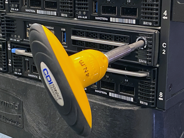
The SX1610 system controller has the receptacle in the center of the assembly.
-
Grasp the front of the system controller and pull toward you to remove it from the chassis.
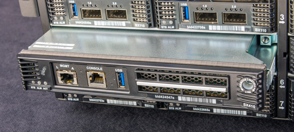
Note: On the SX410 system controller, the perimeter of the system controller should be pulled. On the SX1610 system controller, there are designated pull locations on the left and right.
-
Insert the replacement system controller into the slot.
Slide the system controller in until the jackscrew contacts the mating receptacle in the chassis.
Warning: To avoid damaging the system controller, do not slam it into the chassis!
-
Use the included T-handle 5mm hex torque wrench to turn the jackscrew clockwise to draw the system controller into the chassis to secure the replacement system controller in the chassis.
Keep turning the jackscrew until the T-handle 5mm hex torque wrench clicks, indicating that it has reached the required torque of 4 Newton-meters (35 inch-pounds).
Warning: To avoid damaging the system controller, do not exceed 4 Newton-meters (35 inch-pounds) of torque.
The system controller is now fully inserted.
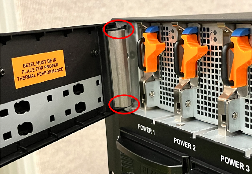
The front bezel with LCD touchscreen on the VELOS chassis is detachable. You can remove the bezel to access the power supply units (PSUs).
Important: This product is sensitive to electrostatic discharge (ESD). F5 recommends that you use proper ESD grounding procedures and equipment when you install or maintain the unit, including attaching a ground strap to the ground strap receptacle location on the front left side of the chassis.
You can change or replace the front bezel with LCD touchscreen in a VELOS chassis as part of the routine maintenance of the unit or in the event of a hardware failure. You do not need special tools and do not need to power down the unit when replacing the front bezel.
Note: All photos shown are examples. The appearance of your components or accessories might vary slightly.
-
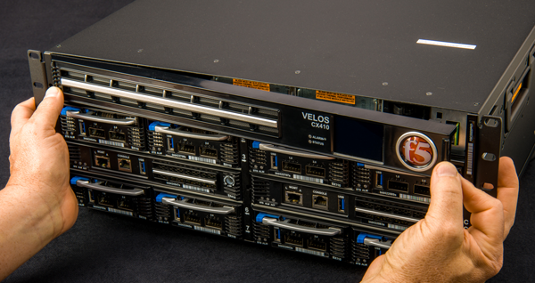
Remove the original front bezel by grasping the bezel using the indentation provided on the right side and pulling out.
-
Pick up the replacement front bezel using the indentations provided.
-
Align the metal tab(s) on the back left side of the replacement bezel with the corresponding cutout(s) on the left side of the chassis, and then rotate the right hand side of the bezel toward the chassis.
-
Press in on the right side until the bezel snaps into place and is secured to the chassis.
CAUTION:
Avoid pinching fingers when installing bezel.
The VELOS chassis supports AC and DC hot-swappable power supply units (PSUs). You can change or replace the PSUs as part of the routine maintenance of the unit, or in the event of a PSU failure.
CAUTION:
Running without power supply units (PSU) installed in all available bays in the platform can affect cooling and electromagnetic interference (EMI). If you must run the unit with one fewer PSU, you must install a blank supply bracket into the empty power supply bay. A blank supply bracket is required to maintain proper airflow in the system. If you do not have a blank supply bracket, leave all supplies installed and disconnect power from any unused PSUs.
CAUTION:
As a safety precaution, the socket outlet must be installed near the equipment and be easily accessible.
CAUTION:
Before installing a DC power supply unit (PSU), be sure that the circuit breaker for the DC mains power to the PSU is switched off.
CAUTION:
Before you begin to work with a DC-powered platform, refer to the DC-powered equipment environmental warnings for this platform and review any safety requirements for the facilities where the DC-powered platforms will be installed.
Important: This product is sensitive to electrostatic discharge (ESD). F5 recommends that you use proper ESD grounding procedures and equipment when you install or maintain the unit, including attaching a ground strap to the ground strap receptacle location on the front left side of the chassis.
Important: You should use only one power supply unit (PSU) type (AC or DC) in a chassis. VELOS chassis are physically designed to prevent using an incompatible PSU type.
Important: F5 strongly recommends that each pair of redundant DC power supply units (PSUs) in the system receives power from independent DC main power sources with independent circuit breakers.
Important: The platform must be installed in a RESTRICTED ACCESS LOCATION, such as a central office or customer premises environment.
Important: To maintain optimal balanced power performance on the CX1610 chassis, it is recommended to distribute the PSUs equally between the top and bottom slots. Here’s are the examples for distribution, based on the number of PSU slots:
- 6 power supply’s: 3 in the top 6 slots and 3 in the bottom 6 slots.
- 8 power supply’s: 4 in the top 6 slots and 4 in the bottom 6 slots.
- 10 power supply’s: 5 in the top 6 slots and 5 in the bottom 6 slots.
- 12 power supply’s: 6 in the top 6 slots and 6 in the bottom 6 slots.
It is recommended to avoid installing PSUs only in the top or bottom slots.
Note: The power supply units (PSUs) do not have an on/off switch. Power is controlled from the rack switchor the mains power source.
Note: After removing input power from any power supply unit (PSU), wait 30 seconds before reapplying input power to the PSU.
Note: Copper cables used for grounding must meet appropriate safety standards.
Note: Bare conductors should be coated with an appropriate antioxidant before being crimped. Make sure to clean all unplated connectors, braided strap, and bus bars to a bright finish prior to coating them with the antioxidant.
Note: The platform must be grounded to a common bonding network (CBN).
Note: The battery return terminals on the platform are in an isolated DC return (DC-I) configuration.
The VELOS CX410 Series chassis supports up to four (4) hot swappable AC power supply units (PSUs).
The VELOS CX1610 Series chassis supports up to twelve (12) hot swappable AC power supply units (PSUs).
The platform supports power redundancy, which ensures that the system is unaffected if a single PSU fails in a system with at least one operating redundant PSU. For a system to be redundant, there must be two or more working supplies if 1-4 blades are installed, or there must be three or more working supplies if 5-8 blades are installed. The system can operate without redundancy at max capacity with two of the four PSUs installed.
In the event of a PSU failure, you can replace a failed AC PSU without powering down the system. For maintenance, you can replace a working PSU, provided that there are working redundant supplies installed in the system.
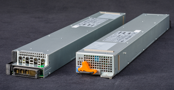
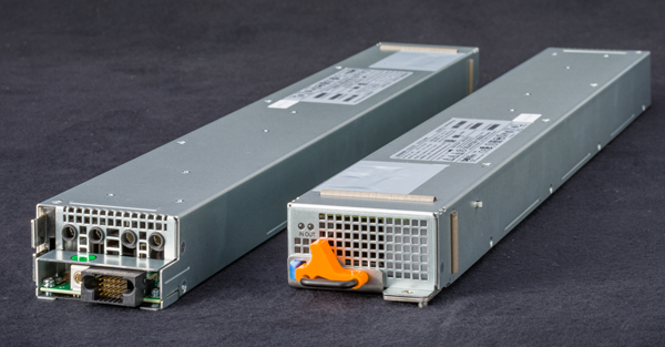
When you add or replace a PSU in your system, be sure to verify the supply’s features and that the PWR-XXXX part numbers match to ensure that you have the correct supply. On the 3000W PSU, you can find the part number on the top of the supply. For the 3000W AC PSU, the part number is PWR-0366.
In the event of a power supply unit (PSU) failure, you can replace an AC PSU in your system. For maintenance, you can hot swap a PSU, provided that there are working redundant supplies installed in the system during the replacement process. If you do not want to hot swap, you can perform the replacement with the system powered off.
Note: All photos shown are examples. The appearance of your power supply units (PSUs) might vary slightly, so be sure to verify the correct PSU part number for your platform.
-
Verify that there are an adequate number of redundant PSUs in your chassis.
There must be two or more working supplies if 1-4 blades are installed. There must be three or more working supplies if 5-8 blades are installed. The system can operate without redundancy at max capacity with two of the four PSUs installed.
Warning: Removing a PSU from a chassis without sufficient power during the replacement process will cause the system to shut down.
-
Remove the LCD bezel from the front of the chassis.
-
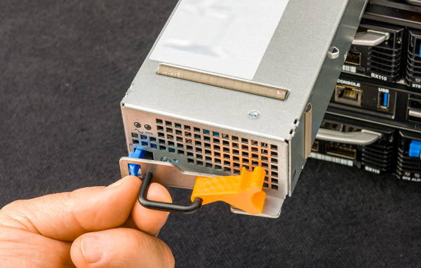
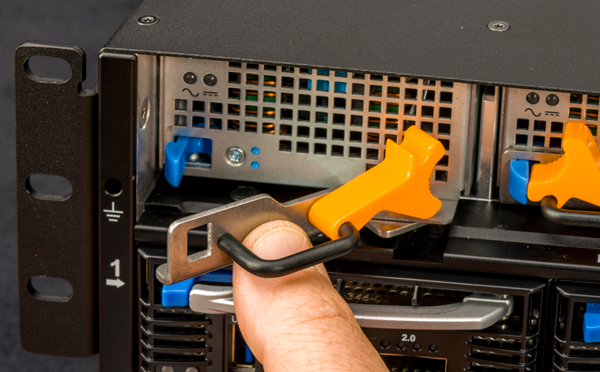
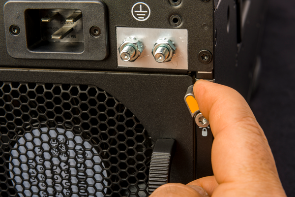
Remove the failed PSU by lifting the orange latch lock, squeezing the blue ejector latch and pulling the handle straight toward you.
Note: After you remove a power supply unit (PSU) from the system, wait at least 30 seconds before you reinstall the PSU. Allow the PSU to fully discharge before you reinstall it.
Note: This image is of a CX410 chassis, but the application is similar for a CX1610 chassis.
-
If an output connector protective cap is installed on your new PSU, remove it before installing the PSU into your system.
-
Inspect the new PSU, especially the connector area and pins, for any damage that might have occurred during shipment.
-
Slide the new PSU into the empty slot, open the ejector handle, push the PSU in until the ejector engages the chassis, and then fully seat the PSU by pushing the latch closed until it clicks.
Note: This image is of a CX410 chassis, but the application is similar for a CX1610 chassis.
-
Secure the orange latch lock.
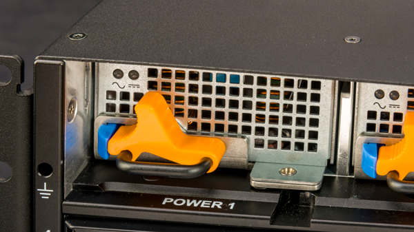
Note: This image is of a CX410 chassis, but the application is similar for a CX1610 chassis.
-
Ensure that the PSU is fully seated in the chassis by making sure it does not come out when gently pulled.
-
Use the LCD touchscreen to clear any alert messages that might have resulted from performing the PSU replacement.
The VELOS CX410 Series chassis supports up to four (4) hot swappable DC power supply units (PSUs).
The VELOS CX1610 Series chassis supports up to twelve (12) hot swappable DC power supply units (PSUs).
The platform supports power redundancy, which ensures that the system is unaffected if a single power supply unit (PSU) fails in a system with at least one operating redundant PSU. In the event of a PSU failure, you can replace a failed DC PSU without powering down the system.
For maintenance, you can replace a working PSU, provided that there are working redundant supplies installed in the system. There must be two or more working supplies if 1-4 blades are installed. There must be three or more working supplies if 5-8 blades are installed. The system can operate without redundancy at max capacity with two of the four PSUs installed.
When you add or replace a PSU in your system, be sure to verify the supply’s features and that the PWR-XXXX part numbers match to ensure that you have the correct supply. On the 3000W PSU, you can find the part number on the top of the supply. For the 3000W DC PSU, the part number is PWR-0367.
In the event of a power supply unit (PSU) failure, you can replace a DC PSU in your system. For maintenance, you can hot swap a PSU, provided that there are working redundant supplies installed in the system during the replacement process. If you do not want to hot swap, you can perform the replacement with the system powered off.
CAUTION:
Be sure that you are using the correct wattage and part number (PWR-0367-xx) of power supply unit (PSU) in all bays, as applicable, when performing a power supply replacement.
Note: All photos shown are examples. The appearance of your power supply units (PSUs) might vary slightly, so be sure to verify the correct PSU part number for your platform.
-
Be sure to switch off the circuit breaker for the PSU to be replaced.
-
Verify that there are an adequate number of redundant PSUs in your chassis.
There must be two or more working supplies if 1-4 blades are installed. There must be three or more working supplies if 5-8 blades are installed. The system can operate without redundancy at max capacity with two of the four PSUs installed.
Warning: Removing a PSU from a chassis without sufficient power during the replacement process will cause the system to shut down.
-
Remove the LCD bezel from the front of the chassis.
-
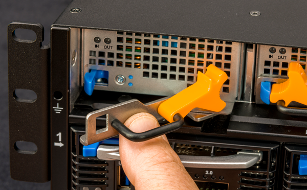
Remove the failed PSU by lifting the orange latch lock, squeezing the blue ejector latch and pulling the handle straight toward you.

Note: This image is of a CX410 chassis, but the application is similar for a CX1610 chassis.
Note: After you remove a power supply unit (PSU) from the system, wait at least 30 seconds before you reinstall the PSU. Allow the PSU to fully discharge before you reinstall it.
-
If an output connector protective cap is installed on your new PSU, remove it before installing the PSU into your system.
-
Inspect the new PSU, especially the connector area and pins, for any damage that might have occurred during shipment.
-
Slide the new PSU into the empty slot, open the ejector handle, push the PSU in until the ejector engages the chassis, and then fully seat the PSU by pushing the latch closed until it clicks.
Note: This image is of a CX410 chassis, but the application is similar for a CX1610 chassis.
-
Secure the orange latch lock.

Note: This image is of a CX410 chassis, but the application is similar for a CX1610 chassis.
-
Ensure that the PSU is fully seated in the chassis by making sure it does not come out when gently pulled.
-
Reapply input power from DC mains power source by switching the circuit breaker back on.
-
Use the LCD touchscreen to clear any alert messages that might have resulted from performing the PSU replacement.
The VELOS chassis supports power supply unit (PSU) controller redundancy, which ensures that the system is unaffected if a single PSU controller fails in a system with one working controller installed. You can change or replace the PSU controller as part of the routine maintenance of the unit, or in the event of a PSU controller failure. For maintenance, you can replace a PSU controller, provided that there is a working PSU controller installed in the system.
Important: This product is sensitive to electrostatic discharge (ESD). F5 recommends that you use proper ESD grounding procedures and equipment when you install or maintain the unit, including attaching a ground strap to the ground strap receptacle location on the front left side of the chassis.
Important: TheCX1610 Series chassis requires at least one upper and one lower PSU controller in order for the system to function.
You can change or replace a power supply unit (PSU) controller in a VELOS chassis as part of the routine maintenance of the unit or in the event of a hardware failure.
Note: All photos shown are examples. The appearance of your components or accessories might vary slightly.
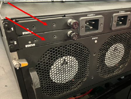
Note: The CX410 chassis has a pair of PSU controllers on the back side of the unit in the upper left corner as shown.
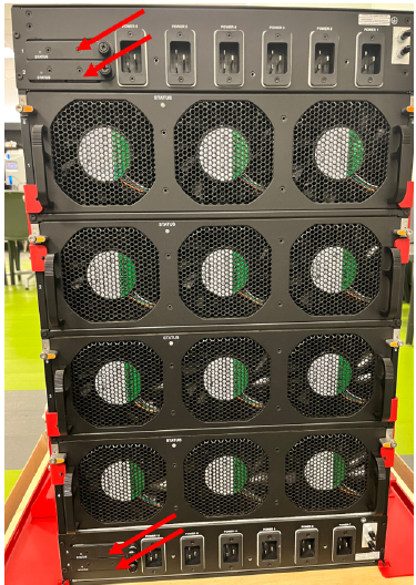
Note: The CX1610 Series chassis has a pair of PSU controllers on the back side of the unit next to the upper power supplies, and another pair on the back side of the unit at the bottom near the lower power supplies.
-
Locate the PSU controllers on the upper left corner of the back of the chassis, or behind the upper and lower bezels.
-
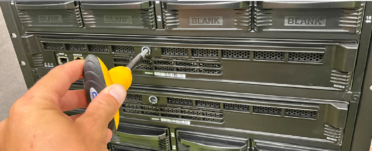
Use a #2 Phillips screwdriver to loosen the screw securing the PSU controller to the chassis.
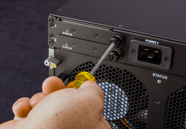
Note: This image is of a CX410 chassis, but the application is similar for a CX1610 chassis.
-
Grasp the captive screw on the PSU controller and pull toward you.
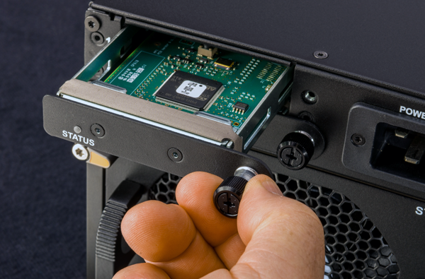
Note: This image is of a CX410 chassis, but the application is similar for a CX1610 chassis.
-
Slide the new PSU controller into the PSU controller slot.
Note: This image is of a CX410 chassis, but the application is similar for a CX1610 chassis.
-
Tighten the captive screws clockwise to 1.0 Newton-meter (9 inch-pounds) to secure it to the chassis completely.
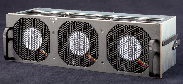
The VELOS chassis has a removable fan tray that is designed to maintain airflow throughout the chassis. You can change or replace the fan tray as part of the routine maintenance of the unit, or in the event of a fan failure. The fans in the fan tray run constantly while the unit is powered on. Over time, the fans can wear out, requiring you to replace the fan tray.
Note: The CX1610 chassis has more than one fan tray; the fan trays should only be replaced one at a time.
Important: This product is sensitive to electrostatic discharge (ESD). F5 recommends that you use proper ESD grounding procedures and equipment when you install or maintain the unit, including attaching a ground strap to the ground strap receptacle location on the front left side of the chassis.
Note: The replacement procedure for fans and cooling units shall be included in the product documentation.
Note: When a fan or cooling unit replacement requires service interruption, the estimated time of replacement by a skilled technician shall be reported.
To ensure that you can easily access the fan tray, route the power cords away from the fan tray so that the cords do not drape over or cross in front of it.
You can change or replace the fan tray in a VELOS chassis as part of routine maintenance of the unit of in the event of a hardware failure. You do not need special tools and do not need to power down the unit when replacing the fan tray.
Note: The CX1610 chassis has four fan trays and they should be replaced one at a time.
CAUTION:
Operating the unit without a fan tray for more than 30 seconds might result in performance throttling or a thermal shutdown of the unit.
-
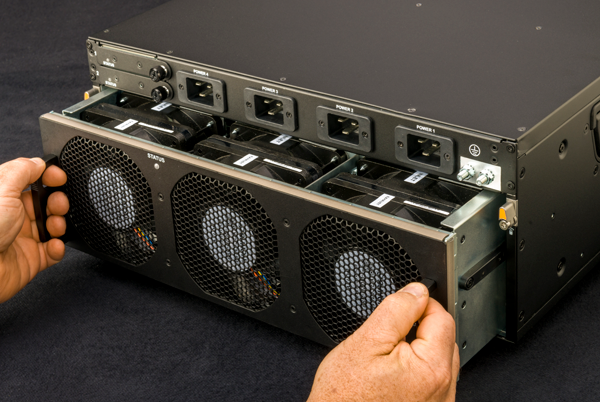
Locate the fan tray on the back of the chassis.
-
Grasp the orange quarter turn latches and rotate them so that they point to the top of the chassis.
-
Remove the fan tray from the chassis by grasping the handles and pulling straight toward you.
Note: This image is of a CX410 chassis, but the application is similar for a CX1610 chassis.
-
Slide the new fan tray into the fan tray slot and push until it fully seats.
The fan tray will automatically power up and begin circulating air through the chassis.
-
Grasp and rotate the quarter turn latches inward to secure the fan tray to the chassis.
Note: This image is of a CX410 chassis, but the application is similar for a CX1610 chassis.