Updated Date: 07/09/2026
Platform Overview
The VELOS CX Series platform is a chassis and blade form factor, designed to meet the needs of large enterprise networking environments that require the ability to process a large volume of application workloads. The hot-swappable blades provide you with the ability to add, remove, or change the platform’s configuration to best fit your network. Many other components are available for you to add, remove, or change including the system controllers, power supply controller, fan tray, LCD bezel, and more. This configuration allows for an extremely robust and flexible system that can manage large amounts of application traffic, and remain operational even if one of its components goes offline.
The VELOS chassis supports either AC or DC power as a pre-installed factory option. The power supply units (PSUs) are hot swappable, but you can use only AC PSUs in an AC-powered chassis and DC PSUs in a DC-powered chassis. You cannot mix AC and DC PSU types in a chassis.
Important: The chassis and blades ship in separate boxes. The system controllers ship inside the chassis. The blades are not designed to be shipped inside a chassis.
VELOS platforms include three main types of hardware components:
- Chassis, which houses the blades, system controllers, and other components.
- System controllers, which provide a unified point for external management and connectivity to the platform and applications running in the chassis. The system controllers also provide a command-line interface (CLI), a webUI, and a REST API.
- Blades, which handle traffic management capabilities, including disaggregation, packet classification, traffic-steering, and more.
VELOS platforms include a new platform layer known as F5OS, which is a combination of the system controllers and chassis partitions.
For more information about installing and upgrading F5OS on your VELOS system, see VELOS Systems: Software Installation and Upgrade at Documentation - F5OS-C and VELOS.
For more information about administering and configuring your VELOS system, see VELOS Systems: Administration and Configuration at Documentation - F5OS-C and VELOS.
The chassis is the housing unit that contains all of the components necessary for the VELOS CX Series platform to operate effectively.
VELOS CX410 and CX1610 chassis are available in DC-powered Network Equipment-Building System (NEBS) compliant versions. For a system to be completely NEBS-compliant, you must use all NEBS-compliant blades in your chassis.
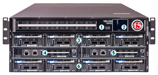
- LCD module LEDs (Status and Alarm)
- LCD touchscreen
- Blades (or Blanks) 1-4
- System controller 1
- System controller 2
- Blades (or Blanks) 4-8
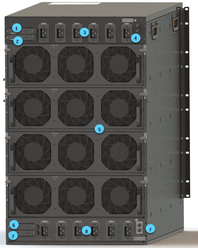
The back of the AC-powered VELOS CX410 chassis includes four AC power receptacles.
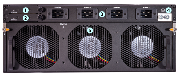
- Power supply controller 1
- Power supply controller 2
- Power supply receptacles (1-4)
- Chassis ground terminals
- Fan tray
The back of the DC-powered VELOS CX410 chassis includes four DC power block terminals.
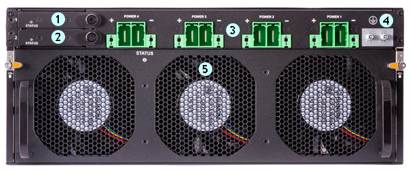
- Power supply controller 1
- Power supply controller 2
- DC power block terminals (1-4)
- Chassis ground terminals
- Fan tray
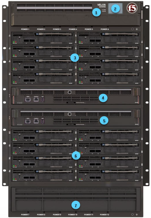
- LCD module LEDs (Status and Alarm)
- LCD touchscreen
- Blade positions (or blanks) 1-16
- System controller 1
- System controller 2
- Blade positions (or blanks) 17-32
- Lower bezel
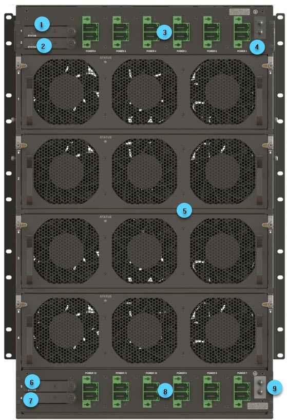
The back of the AC-powered VELOS CX1610 chassis includes 12 AC power receptacles.
- Power supply controller 1
- Power supply controller 2
- Upper power supply receptacles (1-6)
- Upper chassis ground terminals
- Fan trays (1-4)
- Power supply controller 3
- Power supply controller 4
- Lower power supply receptacles (7-12)
- Lower chassis ground terminals
The back of the VELOS CX1610 DC-powered chassis includes 12 DC power block terminals.
- Power supply controller 1
- Power supply controller 2
- Upper power supply receptacles (1-6)
- Upper chassis ground terminals
- Fan trays (1-4)
- Power supply controller 3
- Power supply controller 4
- Lower power supply receptacles (7-12)
- Lower chassis ground terminals
The system controllers provide a high bandwidth interconnect between blades, as well as external management connectivity.
A system controller must be installed in each system controller slot to provide maximum system bandwidth and to provide redundancy. You can use only SX410 Series system controllers in a VELOS CX410 Series chassis, and you can use only SX1610 Series system controllers in a VELOSCX1610 Series chassis.
A jack screw, a type of captive screw, is used to secure the system controller in to the chassis and remove it from the chassis.
Note: Use a 5mm hex driver to remove and install system controller with the jack screw, torque 4 Newton-meter
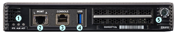
- System controller indicator LEDs
- Management port
- Console port
- USB port
- Jack screw
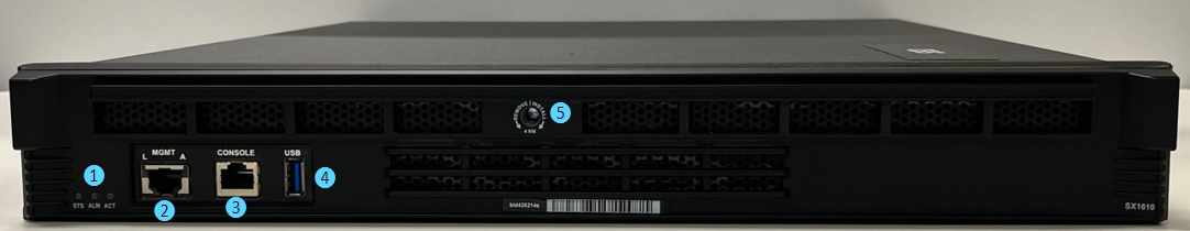
- System controller indicator LEDs
- Management port
- Console port
- USB port
- Jack screw
A blade is the primary component that handles the traffic management within the VELOS platform. You can install up to eight BX110 blades in a VELOS CX410 Series chassis, and up to 16 BX520 blades in a VELOS CX1610 Series chassis. The chassis includes blanks in the slots where blades are not installed.
Important: Blanks must be installed in all unused slots, as they help ensure proper airflow within the chassis and EMI compliance of the unit.
VELOS chassis is available in DC-powered Network Equipment-Building System (NEBS) compliant versions. For a system to be completely NEBS-compliant, you must use all NEBS-compliant components in your chassis.
During initial setup of the chassis, an administrator can group blades into chassis partitions (this is different from TMOS admin partitions). Chassis partitions are a grouping of blades that are completely isolated from other blades/chassis partitions in the system. A blade can belong only to one chassis partition at a time. For the VELOS CX410 Series chassis, a chassis partition can contain up to eight BX110 Series blades. For the VELOS CX1610 Series chassis, a chassis partition can contain up to 16 BX520 Series blades. The system comes preconfigured so that all blades are assigned to a default chassis partition.
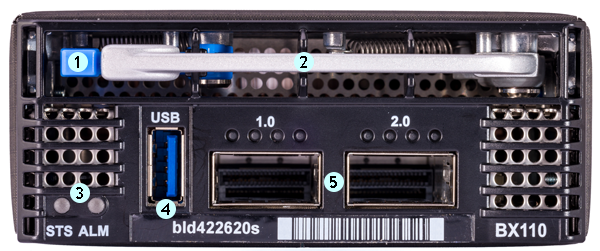
- Latch release
- Ejector handle
- Blade indicator LEDs
- USB port (disabled by default)
- QSFP28 ports (2)
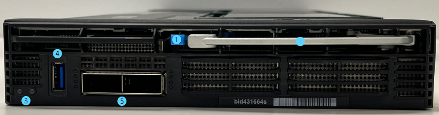
- Latch release
- Ejector handle
- Blade indicator LEDs
- USB port (disabled by default)
- QSFP28 (1.0) (1) and QSFP-DD(2.0) (1)
With VELOS chassis, blades do not have physical console ports. Each system controller has a physical console port. The system controllers in the chassis provide a terminal service that enables authorized users to access blade consoles over SSH using the chassis floating IP address.At a high level, these user roles have terminal service access:
Admin
Users with this role can access any terminals in the chassis.
Resource admin
Users with this role can access any terminals in the chassis.
Terminal server admin
Users with this role have terminal server access to all consoles on the system regardless of partition restrictions.
Operator
Users with this role can access any terminals in the chassis.
Partition
Users with this role are not given access to any terminals in the chassis. Since the chassis terminal service uses SSHD, clients can connect using SSH. The terminal service uses a range of network port numbers to differentiate between connections being requested to the various consoles in the chassis.You can also access any blade console by selecting the desired blade using the Always-On Management (AOM) Command Menu after you connect a serial cable to either of the system controllers’ console ports. For more information about AOM, see the section entitled About Always-On Management.
The VELOS chassis terminal service uses a range of network port numbers to differentiate between connections being requested to either the blade or system controller consoles in a chassis.
| Console | Port number |
|---|---|
| System controller 1 | 7100 |
| System controller 2 | 7200 |
| Blade <1…x> | 700x |
| Blade <1…32> | 70xx |
If you are an authorized user, you can connect to a blade or system controller using the chassis terminal service.
- Connect using SSH to the blade or system controller that you want to access.
ssh <blade-or-sys-controller-ip-address> -l admin -p <port-number>This example opens an SSH session to an IPv4 address as an admin user to the blade in slot 1:
ssh 192.0.2.10 -l admin -p 7001This example opens an SSH session to an IPv4 address as an admin user to the system controller in slot 2:
ssh 192.0.2.10 -l admin -p 7200This example opens an SSH session to an IPv6 address as an admin user to the blade in slot 4:
ssh 2001:db8:ffff:100::1 -l admin -p 7004If there is not already an active terminal session attached to the specified console, you are connected immediately. If there is already an active terminal session attached, you can choose to terminate the existing terminal session and replace it.
When you complete your terminal session to a blade or a system controller, you can terminate your session by typing the Enter ~. (tilde period) command sequence.
The LCD touchscreen includes a Health menu, which enables you to run LCD tests.
You can use the Health menu to run LCD tests.
| Option | Description |
|---|---|
| Run LCD Tests | Performs tests for the logo ball test and system LEDs. |
The behavior of the various LEDs on the platform indicate the status of the system or component.
The Status LED indicates the operating state of the system controller.
| State | Description |
|---|---|
| off/none | System controller is powered down. |
| green solid | System is running in normal mode. |
| yellow/amber solid | Host is not functional. |
| yellow/amber blinking | AOM is not functional. |
The Alarm LED indicates the current alert status for a system controller.
There are five levels of messages.
| State | Description |
|---|---|
| off/none | No active alarms. |
| yellow/amber solid | Warning. System may not be operating properly, but the condition is not severe or potentially damaging. |
| yellow/amber blinking | Error. System is not operating properly, but the condition is not severe or potentially damaging. |
| red solid | Critical. System is not operating properly, and the condition is potentially damaging. |
| red blinking | Emergency. System is not operating, and the condition is potentially damaging. |
The Active LED indicates the activity state of the system controller.
| State | Description |
|---|---|
| off/none | The system controller is unpowered, has failed, or is not active. |
| green solid | The system controller is active and primary. |
The Status LED indicates the operating state of a blade.
| State | Description |
|---|---|
| off/none | Blade is not powered. |
| green solid | Blade is fully functional. |
| yellow/amber solid | Host CPU is not functional. |
| yellow/amber blinking | AOM is not functional. |
| blue blinking | Blade locator function is enabled. |
The Alarm LED indicates the current alert status for a blade.
There are five levels of messages.
| State | Description |
|---|---|
| off/none | No active alarms. |
| yellow/amber solid | Warning. System may not be operating properly, but the condition is not severe or potentially damaging. |
| yellow/amber blinking | Error. System is not operating properly, but the condition is not severe or potentially damaging. |
| red solid | Critical. System is not operating properly, and the condition is potentially damaging. |
| red blinking | Emergency. System is not operating, and the condition is potentially damaging. |
The Status LED indicates the operating state of the chassis infrastructure.
| State | Description |
|---|---|
| off/none | The chassis is completely unpowered, or the LCD module has failed. |
| green solid | LCD module is operational, and no chassis infrastructure faults are present. |
| yellow/amber solid | LCD module is in the process of booting its application code and is not yet operational or a chassis infrastructure fault is present. Examples of chassis infrastructure components include: system controller, PSU, fan tray, etc. |
| yellow/amber blinking | LCD module has lost communication to the platform for more than one minute. |
The Alarm LED indicates the current alert status for the system. There are five levels of messages.
| State | Description |
|---|---|
| off/none | No active alarms, the platform is completely unpowered, or the LCD module has failed. |
| yellow/amber solid | Warning. System may not be operating properly, but the condition is not severe or potentially damaging. |
| yellow/amber blinking | Error. System is not operating properly, but the condition is not severe or potentially damaging. |
| red solid | Critical. System is not operating properly, and the condition is potentially damaging. |
| red blinking | Emergency. System is not operating, and the condition is potentially damaging. |
The F5 logo ball LED indicates whether the system is powered on and if the chassis locator function is enabled.
There are three status levels.
| State | Description |
|---|---|
| on | System is powered on. |
| blinking | Chassis locator function is enabled. |
| off | System is completely powered off. |
The Status LED indicates the operating state of the fan tray.
| State | Description |
|---|---|
| off/none | The system is not powered, or a system fault prevents the fan controller status LED from being driven properly. |
| yellow/amber solid | Fan controller is in initial power up, or the fan controller is not reachable. |
| yellow/amber blinking | Fan controller is in bootloader mode. |
| green solid | Fan controller is initialized and functioning properly. |
The LEDs on the power supply unit (PSU) controller indicate the status of the controller..
| LED behavior | PSU controller status |
|---|---|
| off/none | System is not powered or a system fault prevents the PSU controller status LED from being driven properly. |
| yellow/amber solid | PSU controller is in initial power up or the PSU controller is not reachable. |
| yellow/amber blinking | PSU controller is in bootloader mode. |
| green solid | PSU controller is initialized and functioning properly. |
The LEDs located on the AC power supply units (PSUs) indicate the operating state of the supplies.
| Input LED | Output LED | Condition |
|---|---|---|
| green solid | green solid | Normal operation |
| off | off | Fault: Input UV, Input OV, VSB SC |
| off | yellow/amber solid | Not valid |
| green solid | yellow/amber solid | Warning: VSB OC Fault: Fan, OTP, OC, VOUT OV/UV |
| green solid | yellow/amber blinking | Warning: FAN, OTP, OC, VOUT OV/UV |
| green blinking | yellow/amber solid | Fault: Input OV |
| green blinking | yellow/amber blinking | Warning: Input OV, Input UV |
| green blinking | off | Not valid |
| green solid | green blinking | PS_ON_L is high |
| green solid | off | PS_KILL PSU not inserted |
The LEDs located on the DC power supplies indicate the operating state of the power supplies
| Input LED | Output/Fault LED | Condition (PUB-0342-01 and later) |
|---|---|---|
| green solid | green solid | Normal operation |
| off | off | Fault: Input UV |
| off | yellow/amber solid | Not valid |
| green solid | yellow/amber solid | Fault: Fan, OTP, OC, VOUT OV/UV, VSB OV/UV |
| green solid | yellow/amber blinking | Warning: FAN, OTP, OC, VOUT OV/UV, VSB OV/UV |
| green blinking | yellow/amber solid | Fault: Input OV |
| green blinking | yellow/amber blinking | Warning: Input OV/UV |
| green blinking | off | Not valid |
| green solid | green blinking | PS_ON_L is high |
| green solid | off | PS_KILL PSU not inserted |
OV - Over Voltage; OTP - Over Temperature Protection; UV - Under Voltage; OC - Over Current; VSB - Standby Voltage
VELOS Series platforms include multiple interfaces on the system controllers and the blades. You can enable or disable front panel management interfaces on the system controllers. You can also configure settings or properties on 100GbE interfaces on blades, such as enabling or disabling the interface, configuring port speed, Ethernet flow control, and more.
VELOS system controllers include a 10GbE front-panel management port. You refer to the front-panel management port using the name
Redundant Mode
Only the Active system controller’s management port forwards traffic. The management port on the standby will show an Admin state and operational state of UP, but will not forward management traffic; it remains a standby. Redundant Mode is the default.
Aggregated Mode
The management ports of both system controllers function as a single 802.3ad aggregated port. The system controller supports two modes of aggregation: STATIC and LACP.
You should use LACP aggregation whenever possible, as LACP aggregation management is superior to STATIC aggregation management.
Enable/disable the management port via the serial console only to prevent potential SSH inaccessibility to the system controller.
You can enable a specified management port from the system controller CLI.
Important: The system controller management ports are enabled by default. If the management ports are disabled, it may not be possible to connect to the system controller CLI using SSH and the floating IP address. In this situation, the management ports may be enabled by connecting to the Active system controller through the active system controllers serial console.
-
Connect using SSH to the system controller floating management IP address.
-
Log in to the command line interface (CLI) of the system controller using an account with admin access.
When you log in to the system, you are in user (operational) mode.
-
Change to config mode.configThe CLI prompt changes to include (config).
-
Enable the specified management port.
interfaces interface <system-controller-slot>/mgmt0 config enabledIn this example, you enabled the management port on system controller 2:
syscon-1-active(config)# interfaces interface 2/mgmt0 config enabledThe system controller management port shows an operational state of UP.
You can disable a specified management port from the system controller CLI.
-
Connect using SSH to the system controller floating management IP address.
-
Log in to the command line interface (CLI) of the system controller using an account with admin access.
When you log in to the system, you are in user (operational) mode.
-
Change to config mode.
configThe CLI prompt changes to include (config).
-
Disable the specified management port.
interfaces interface <system-controller-slot>/mgmt0 config disabledIn this example, you disabled the management port on system controller 2:
syscon-1-active(config)# interfaces interface 2/mgmt0 config disabledThe system controller management port shows an operational state of DOWN.
Each system controller has one 10GB management port. You can aggregate the management ports on both system controllers in your chassis so that they operate as a single 20Gbps 802.3ad aggregated port from the chassis partition CLI. The system controller supports two aggregation modes: STATIC and LACP (recommended). You can define only one management port aggregation.
-
Connect to the system using a management console or console server.
The default baud rate and serial port configuration is 19200/8-N-1.
-
Log in to the command line interface (CLI) of the system controller using an account with admin access.
When you log in to the system, you are in user (operational) mode.
-
Change to config mode.
configThe CLI prompt changes to include (config).
-
Create an aggregated interface.
syscon-1-active(config)# interfaces interface <aggregation-name> config type ieee8023adLag name <aggregation-name>In this example, you create an aggregation named “lag-test”:
syscon-1-active(config)# interfaces interface lag-test config type ieee8023adLag lag-test -
Configure a type or mode for the aggregation.
syscon-1-active(config)# interfaces interface <aggregation-name> aggregation config lag-type [LACP | STATIC]In this example, you configure an aggregation named “lag-test” to use LACP as the aggregation type:
syscon-1-active(config)# interfaces interface lag-test aggregation config lag-type LACP -
Add both of the management ports to the aggregation.
syscon-1-active(config)# interfaces interface 1/mgmt0 ethernet config aggregate-id <aggregation-name>

syscon-1-active(config)# interfaces interface 2/mgmt0 ethernet config aggregate-id <aggregation-name>
In this example, you add both management ports to an aggregation named “lag-test”:
syscon-1-active(config)# interfaces interface 1/mgmt0 ethernet config aggregate-id lag-test syscon-1-active(config)# interfaces interface 2/mgmt0 ethernet config aggregate-id lag-test -
Configure a type or mode for interface.
syscon-1-active(config)# lag-type [LACP | STATIC] interfaces
interface <aggregation-name> config name <aggregation-name>
In this example, you configure an aggregation named “lag-test” to use LACP as the aggregation type:
syscon-1-active(config)# lacp interfaces interface lag-test config name lag-test
You can disable an aggregated interface by removing the management ports from the aggregation from the chassis partition CLI.
-
Connect using SSH to the system controller floating management IP address.
-
Log in to the command line interface (CLI) of the chassis partition using an account with admin access.
When you log in to the system, you are in user (operational) mode.
-
Change to config mode.
configThe CLI prompt changes to include (config).
-
Disable an aggregated interface by removing the management ports from a specified aggregation.
syscon-1-active(config)# no interfaces interface 1/mgmt0 ethernet config aggregate-id

syscon-1-active(config)# no interfaces interface 2/mgmt0 ethernet config aggregate-id
In this example, you delete an aggregation named “lag-test”:
syscon-1-active(config)# no interfaces interface lag-test -
Disable a type or mode for the aggregation.
syscon-1-active(config)# no [LACP | STATIC]interfaces interface aggregate-idIn this example, you delete an aggregation named “lag-test”:
syscon-1-active(config)# no lacp interfaces interface lag-test
You can delete an aggregated interface from the chassis partition CLI.
Connect using SSH to the system controller floating management IP address. Log in to the command line interface (CLI) of the chassis partition using an account with admin access.When you log in to the system, you are in user (operational) mode. Change to config mode.configThe CLI prompt changes to include (config).
Delete an aggregated interface.
syscon-1-active(config)# no interfaces interface
syscon-1-active(config)# no interfaces interface lag-testYou can use only F5-branded transceiver modules. On BX110, both ports default to 100GbE. On BX520, port 1 defaults to 100GbE mode, and port 2 defaults to 400GbE mode. For more information about supported transceiver modules and cable requirements, see Transceiver Modules at techdocs.f5.com/en-us/hw-platforms/f5-plat-hw-essentials.html. On BX110, you can break out the 100GbE or 40GbE bundle and use them as individual 10GbE ports using a QSFP+ breakout cable. This cable has a female MPO/MTP connector at one end, which connects to the QSFP+ port, and four LC duplex connectors at the other end, which connect to SFP+ modules on an upstream switch. If you are using a breakout cable for 10GbE connectivity, you should use the supported distance as detailed in the Specifications for fiber QSFP+ modules section and not the Specifications for fiber SFP+ modules section of the F5 Platforms: Accessories guide at techdocs.f5.com/en-us/hw-platforms/f5-plat-accessories.html.
You can show the state of a specified front-panel interface from the chassis partition CLI.
-
Connect using SSH to the system controller floating management IP address.
-
Log in to the command line interface (CLI) of the chassis partition using an account with admin access.
When you log in to the system, you are in user (operational) mode.
-
Show the state of a specified interface.
show interfaces interface <blade-number>/<interface-number> stateIn this example, you show information about blade 1/interface 1:
default-1# show interfaces interface 1/1.0 state
state type ethernetCsmacd
state mtu 9600
state enabled true
state oper-status UP
state forward-error-correction auto
state lacp_state LACP_DEFAULTED
You can show the state of all interfaces from the chassis partition CLI.
-
Connect using SSH to the system controller floating management IP address.
-
Log in to the command line interface (CLI) of the chassis partition using an account with admin access.
When you log in to the system, you are in user (operational) mode.
-
Show the state of all interfaces.
show interfaces interface statePossible completions include:
counters
disabled
enabled
ifindex
name
oper-status
type
forward-error-correction
mtu
In this example, you show information about blade 1/interface 1:
default-1# show interfaces interface 1/1.0 state
state type ethernetCsmacd
state mtu 9600
state enabled true
state oper-status UP
state forward-error-correction auto
state lacp_state LACP_DEFAULTED
In this example, you show the FEC state of all interfaces:
default-1# show interfaces interface state forward-error-correction
You can show statistics for all interfaces from the chassis partition CLI.
-
Connect using SSH to the system controller floating management IP address.
-
Log in to the command line interface (CLI) of the chassis partition using an account with admin access.
When you log in to the system, you are in user (operational) mode.
-
Show statistics for all interfaces.
show interfaces interface state countersPossible completions include:
in-broadcast-pkts
in-discards
in-errors
in-fcs-errors
in-multicast-pkts
in-octets
in-unicast-pkts
out-broadcast-pkts
out-discards
out-errors
out-multicast-pkts
out-octets
out-unicast-pkts
In this example, you show statistics for all interfaces:
default-1# show interfaces interface state counters
You can show the current running configuration for all interfaces from the chassis partition CLI.
-
Connect using SSH to the system controller floating management IP address.
-
Log in to the command line interface (CLI) of the chassis partition using an account with admin access.
When you log in to the system, you are in user (operational) mode.
-
Show the current running configuration for all interfaces.
show running-config interfaces interface
You can show the current running configuration of VLAN interface members from the chassis partition CLI.
-
Connect using SSH to the system controller floating management IP address.
-
Log in to the command line interface (CLI) of the chassis partition using an account with admin access.
When you log in to the system, you are in user (operational) mode.
-
Show the current running configuration of VLAN interface members.
show running-config interfaces interface ethernet switched-vlan
You can reset counters for specified interfaces from the chassis partition CLI.
-
Connect using SSH to the system controller floating management IP address.
-
Log in to the command line interface (CLI) of the chassis partition using an account with admin access.
When you log in to the system, you are in user (operational) mode.
-
Change to config mode.
configThe CLI prompt changes to include (config).
-
Reset counters for specified interfaces.
reset counters interfaces [<blade-number/interface-number>]In this example, you reset counters for blade 1/interface 1 and blade 1/interface 2:
default-1(config)# reset counters interfaces 1/1.0 1/2.0 -
Commit the configuration changes.
commit
You can create a LAG interface from the chassis partition CLI.
-
Connect using SSH to the system controller floating management IP address.
-
Log in to the command line interface (CLI) of the chassis partition using an account with admin access.
When you log in to the system, you are in user (operational) mode.
-
Change to config mode.
configThe CLI prompt changes to include (config).
-
Create a LAG interface.
interfaces interface <lag-name> configPossible completions include:
aggregation
config
hold-time
In this example, you create an IEEE 802ad LAG interface named “new-lag”:
interfaces interface new-lag config type ieee802adLag -
Commit the configuration changes.
commit
You can create either a static or LACP LAG interface from the chassis partition CLI.
-
Connect using SSH to the system controller floating management IP address.
-
Log in to the command line interface (CLI) of the chassis partition using an account with admin access.
When you log in to the system, you are in user (operational) mode.
-
Change to config mode.
configThe CLI prompt changes to include (config).
-
Create a LAG interface with a specified type.
interfaces interface <lag-type> configPossible completions include:
LACP
static
In this example, you create a static LAG interface:
default-1(config)# aggregation config lag-type STATIC -
Commit the configuration changes.
commit
You can show the current running configuration for LAG interfaces from the chassis partition CLI.
-
Connect using SSH to the system controller floating management IP address.
-
Log in to the command line interface (CLI) of the chassis partition using an account with admin access.
When you log in to the system, you are in user (operational) mode.
-
Show the current running configuration for LAG interfaces.
show running-config interface <lag-name> aggregation
You can associate an interface with a specified LAG from the chassis partition CLI.
-
Connect using SSH to the system controller floating management IP address.
-
Log in to the command line interface (CLI) of the chassis partition using an account with admin access.
When you log in to the system, you are in user (operational) mode.
-
Change to config mode.
configThe CLI prompt changes to include (config).
-
Associate an interface with a specified LAG.
interfaces interface <blade-number/interface-number> ethernet config aggregate-id <lag-name>In this example, you associate blade 1/interface 1.0 with a LAG named “new-lag”:
default-1(config)# interfaces interface 1/1.0 ethernet config aggregate-id new-lag -
Commit the configuration changes.
commit
The appearance and behavior of the network interface LEDs on the platform indicate network traffic activity and interface speed.
The system controller management port supports 10GbE/1GbE/100MbE connectivity. The appearance and behavior of the system controller management port LEDs indicate the link and activity status.
| LED | State | Description |
|---|---|---|
| link | off/none | Not linked. |
| green solid | Linked at 10GbE. | |
| yellow/amber solid | Linked at 1GbE or 100MbE. | |
| activity | off/none | Not linked or link is idle. |
| green blinking | Link is actively transmitting or receiving data. |
The appearance and behavior of the port LEDs indicate the link and activity status.
| State | Module | Description |
|---|---|---|
| off (not lit) | QSFP+ or QSFP28 | No link. |
| blue solid | QSFP28 | Linked at 100GbE (with all four LEDs operating in unison). |
| blue blinking | QSFP28 | Link is actively transmitting or receiving data at 100GbE (with all four LEDs operating in unison). |
| green solid | QSFP+ | Linked at 40GbE when operating as a single 40GbE port (with all four LEDs operating in unison). |
| green blinking | QSFP+ | Link is actively transmitting or receiving data at 40GbE (with all four LEDs operating in unison). |
| yellow/amber solid | QSFP+ | Linked at 10GbE when operating as four 10 GbE ports. |
| yellow/amber blinking | QSFP+ | Link is actively transmitting or receiving data at 10GbE. |
BX520 port LED behavior The appearance and behavior of the QSFP-DD port LEDs indicate the link and activity status.
| State | Module | Description |
|---|---|---|
| off (not lit) | QSFP-DD | No link. |
| blue solid | QSFP-DD | Linked at 400GbE (with all four LEDs operating in unison). |
| blue blinking | QSFP-DD | Link is actively transmitting or receiving data at 400GbE (with all four LEDs operating in unison). |
| green solid | QSFP28 | Link is actively transmitting or receiving data at 100GbE (with all four LEDs operating in unison). |
| green blinking | QSFP28 | Link is actively transmitting or receiving data at 100GbE (with all four LEDs operating in unison). |
The front-panel ports on a VELOS BX110 Series Series blade support port group functionality. Port groups enable you to change which mode, or port speed, that port uses. QSFP28 ports operate at 100GbE by default, but depending on the optical transceiver module that you have installed in the port, you can configure the port group to use one of these modes:
100GbE mode
Creates one interface at 100G speed. This is the default mode for 100G ports.
40GbE mode
Creates one interface at 40G speed. This is the default mode for 40G ports.
4x25GbE breakout mode
Creates four interfaces at 25G speed.
4x10Gb breakout mode
Creates four interfaces at 10G speed.
VELOS BX110 Series blades support homogeneous port groups per blade, which means that if you want to change the speed of a port group, you must change the mode for both port groups on a blade.
Changing the mode for a port group reboots the blade, removes stale interfaces from your configuration, and removes any references to stale interfaces from your configuration. You will then need to reconfigure any previously-configured protocols to use the modified port group.
If you are going from QSFP28/QSFP+ ports to SFP ports where the SFP ports are individual 10G/25G optical transceiver modules, you must use a breakout cable to split the single interface into multiple interfaces, and then configure your blade to use one of the breakout modes.
The VELOS BX520 blade supports homogeneous and limited mixed portgroup mode combinations per blade. You can configure the port groups using the specific port group combination. Available port groups combination for the interfaces on BX520:
| Port Group | Option | Description |
|---|---|---|
| Port group 1 | 100GbE | Creates one interface at 100G |
| 4 x 100GbE | Creates four interfaces at 100G speed (requires the use of a breakout cable). | |
| Port group 2 | 400GbE | Creates one interface at 400G |
| 4 x 100GbE | Creates four interfaces at 100G speed (requires the use of a breakout cable). |
If you are using QSFP28/QSFP+ optical transceivers in your VELOS BX110 Series blade and connecting to other QSFP28/QSFP+ ports, you don’t need to use a breakout cable to use one of the breakout modes. If you are connecting to SFP/SFP+ ports where the ports are individual 10G/25G optical transceiver modules, you must use a breakout cable to split the single interface into multiple interfaces, and then configure your blade to use one of the breakout modes.
The system creates and breaks down interfaces based on how you have configured port groups.
| Optical transceiver module | Port group mode | Interfaces |
|---|---|---|
| QSFP28 | 100G | x.0 |
| 100G | 4x25G | |
| 100G | x.1, x.2, x.3, x.4 | |
| QSFP+ | 40G | x.0 |
| 40G | 4x10G | |
| 40G | x.1, x.2, x.3, x.4 |
The system creates and breaks down interfaces based on how you have configured port groups.
| Optical transceiver module | Port group mode | Interfaces |
|---|---|---|
| QSFP28 | 100G | 1.0 |
| QSFP28 | 100G | 4x100G |
| QSFP-DD | 400G | 2.0 |
| QSFP-DD | 400G | 4x100G |
4x100G
For BX110 blades, you can configure a port group for the interfaces on the blade at either 100GbE or 40GbE speeds from the chassis partition CLI. You can also break out the ports to either 4x25GbE or 4x10GbE.
VELOS BX520 blades support homogeneous port groups per blade, which means that if you want to change the speed of a port group you must change the mode for both port groups on a blade.
-
Connect using SSH to the chassis partition management IP address.
-
Log in to the command line interface (CLI) of the chassis partition using an account with admin access. When you log in to the system, you are in user (operational) mode.
-
Change to config mode.configThe CLI prompt changes to include (config).
-
Configure port groups for a specific blade/interface pair.
-
For BX110 Blades:
portgroups portgroup <blade-number>/<interface-number> config mode [MODE_100GB | MODE_4x25GB | MODE_40GB | MODE_4x10GB | MODE_400GB]In this example, you configure the port group mode on a BX110 blade, on blade 1/interface 2 to use the 40GB mode:
default-1(config)# portgroups portgroup 1/2 config mode MODE_40GB -
For BX520 Blades: You can configure the port groups using the specific port group combination.
portgroups portgroup <blade-number>/<interface-number> config mode [MODE_100GB | MODE_4x10GB]portgroups portgroup <blade-number>/<interface-number> config mode [MODE_400GB | MODE_4x10GB]In this example, with the default running configuration donot allow changing the mode of only one of the portgourps.
default-1# show running-config portgroups
portgroups portgroup 5/1
config mode MODE_100GB
config ddm ddm-poll-frequency 30
!
portgroups portgroup 5/2
config mode MODE_400GB
config ddm ddm-poll-frequency 30
!
default-1# config
Entering configuration mode terminal
default-1(config)# portgroups portgroup 5/1 config mode MODE_4x100GB
default-1(config-portgroup-5/1)# commit
Aborted: 'portgroups portgroup': Homogeneous and limited mixed portgroup mode combinations are supported per blade. The portgroups from blade(s) 5 do not follow the constraint.
default-1(config-portgroup-5/1)
Commit the configuration changes.commit
Verify the port groups configuration. show portgroups portgroup
The Always-On Management (AOM) subsystem on the system controller enables you to manage the system remotely from the serial console, even if a blade is powered down. The AOM Command Menu operates independently of the VELOS host operating system.
When you run the AOM Command Menu, the serial connection to the blade CPU is interrupted for the duration of time that the Command Menu is active. You can use the command menu to reset the unit if the host has locked up or get access to a blade directly, so that you can configure it from the command-line interface (CLI).
When you access the AOM Command Menu, it displays the Active console, which blade’s console is currently connected, and the Physically connected console, which is how you are physically connected to the system (for example, serial port/console or the management port of one of the system controllers).
In this example, you are connected to the console of the blade in slot 1 and are connected to the serial port of the system controller in slot 1.
Active console : blade 1
Physically connected console : system controller 1 serial port

AOM Command Menu:
D --- Disconnect blade console
I --- Display blade information
P --- Power on/off blade
R --- Reset blade CPU
U --- Front panel USB port
Q --- Quit menu and return to console

Enter Command:You can access the AOM Command Menu after connecting to the system controller using the front panel serial console.
-
Connect to the system using the serial console.
-
Open the AOM Command Menu. Esc ( The system displays the AOM Command Menu, the active console, and physically-connected console:
[root@controller-1 ~]#
Active console : system controller 1
Physically connected console : system controller 1 serial port
AOM Command Menu:
B --- Set baud rate
C --- Capture blade console
CC -- Capture system controller console
I --- Display chassis information
P --- Power on/off blade
PC -- Power on/off system controller
R --- Reset blade CPU
RC -- Reset system controller CPU
U --- Front panel USB port
Q --- Quit menu and return to console
Enter Command:
The AOM Command Menu provides the AOM options for the platform. You can access the AOM Command Menu using either a serial console or SSH via the chassis terminal service.
The availability of menu options varies depending on the platform type.
| Letter | Option | Description |
|---|---|---|
| D | Disconnect blade console | Disconnects a previously established serial console redirection to a blade. This returns the user console to the originating connection—either the system controller AOM if you are connected to the front panel serial port or the system controller’s terminal service (if you connected through the system controller’s management interface). |
| I | Display blade information | Displays information about the blade, including: |
| * AOM firmware version | ||
| * AOM bootloader version | ||
| * CPLD version | ||
| * Serial number | ||
| * Power status | ||
| * Status LED status | ||
| * Alarm LED status | ||
| * Power on self-test status | ||
| * Runtime status | ||
| P | Power on/off blade | Powers the blade on or off. Depending on whether there is sufficient power in the chassis to power on the blade, the AOM may be unable to power up the blade. You can choose to forcibly power on the blade and will have to confirm that you want to power on the blade in this condition. F5 strongly recommends, however, that you install or apply power to additional power supply units (PSUs) in the chassis. Forcibly powering on a blade in this condition might cause a full chassis outage. |
| R | Reset blade CPU | Resets the blade’s CPU. F5 does not recommend using this option under normal circumstances. It does not allow for graceful shutdown of the system. |
| U | Front panel USB port | Enables or disables the front panel USB port on a blade. The front panel USB port on blades are disabled by default. |
| Q | Quit menu and return to console | Exits the AOM Command Menu and returns to the blade’s CPU console. |