Updated Date: 07/07/2026
Deploying Route Domains within a vCMP Guest
With a vCMP® system, you typically create guests as a way to segment different types of application traffic. An alternative way to segment application traffic is to configure a feature known as route domains, within a single guest.
A route domain is a configuration object that isolates network traffic for a particular application on the network. Using route domains, you can assign the same IP address or subnet to multiple nodes on a network, provided that each instance of the IP address resides in a separate route domain.
The configuration described here manages traffic for three separate customers, where each customer has its own route domain to process and ensure isolation for a different type of application traffic. By using route domains within a guest, you can minimize the total number of guests you must create to manage customer traffic.
This illustration shows a redundant system configuration in which a single guest uses route domains for three separate customers.
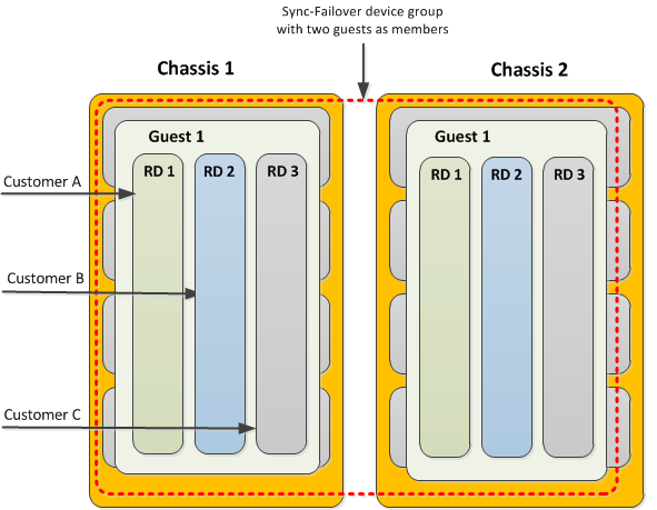
Each route domain contains all of the network objects necessary for processing a specific type of traffic and ensuring failover to the other guest in the event that the system becomes unavailable. These network objects consist of floating self IP addresses associated with host-based VLANs, floating virtual IP addresses, and pool members defined on the guest. The floating addresses are further associated with an active traffic group on one instance of the guest and a standby traffic group on the other instance of the guest.
Before you begin deploying route domains within a vCMP guest, ensure that you have configured the following on each chassis:
- The initial setup of the BIG-IP® base network on the VIPRION® chassis, prior to provisioning the system for vCMP®. This setup typically includes VLANs for the external and internal networks, as well as an additional internal VLAN for failover communications between device group members.
- The initial setup of the vCMP host. This includes provisioning the system for vCMP and creating guests, with the host VLANs published to the guest.
- Non-floating self IP addresses on the guest. These addresses are associated with the host-based external, internal, and high availability VLANs.
- A Sync-Failover device group consisting of two guests as its members (one guest per chassis). The guests on the two chassis should be identical with respect to memory, CPU, and slot allocation.
When you initially configured the BIG-IP® base network on the VIPRION® system, you created three VLANs: two for the internal and external networks, and one for high availability communications, and you created their associated non-floating self IP addresses. Now you are ready to create additional VLANs and self IP addresses for processing each customer’s application traffic. On a system provisioned for vCMP®, all VLANs reside on the vCMP host, while all self IP addresses (floating and non-floating) reside on the guest.
This illustration shows the relationship of the VLANs on the host to the IP addresses within each route domain on the guest. Note that in our example, all three customers use the same self IP and virtual IP addresses but with unique route domain IDs. Also note that except for the non-floating self IP addresses in partition Common, the entire configuration is duplicated on the peer guest (not shown).
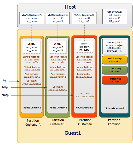
In this illustration:
- Blue text
- Objects created by host administrator.
- Black text
- Objects created by guest administrator.
- Brown text
- Objects created by customer administrator.
To set up a route domain configuration, the vCMP® host administrator needs to create VLANs for use by each customer.
On the host, for our sample configuration with three customers, you create a separate set of uniquely-tagged internal and external VLANs for each customer. You will therefore create at least six VLANs on the host (two per customer) that, when combined with the three existing VLANs, bring the total number of VLANs on the host to nine. At this point, all VLANs reside in partition Common. Then you assign all nine host-based VLANs to the guest. This allows the guest to use those VLANs to process customer traffic.
To summarize, the objects that a host administrator creates are:
- VLANs created during base VIPRION® configuration
- Customer-specific VLANs for use by guest route domains
You create additional VLANs on the vCMP host that you then assign to the guest. Then, when logged in to the guest, you can selectively distribute the VLANs to different route domains within the guest. Each route domain corresponds to a different customer.
Note: You must create this same set of VLANs on the host of each vCMP system in the configuration.
Important: Ensure that the tags for all VLANs that you create are unique.
-
On the Main tab, click Network > VLANs.
The VLAN List screen opens.
-
Click Create.
The New VLAN screen opens.
-
In the Name field, type the name of the first VLAN.
-
In the Tag field, type a numeric tag, between 1-4094, for the VLAN, or leave the field blank if you want the BIG-IP system to automatically assign a VLAN tag.
The VLAN tag identifies the application traffic for the associated VLAN.
Important: Each VLAN tag that you specify in this field must be unique on the vCMP system.
-
If you want to use Q-in-Q (double) tagging, use the Customer Tag setting to perform the following two steps. If you do not see the Customer Tag setting, your hardware platform does not support Q-in-Q tagging and you can skip this step.
-
From the Customer Tag list, select Specify.
-
Type a numeric tag, from 1-4094, for the VLAN.
The customer tag specifies the inner tag of any frame passing through the VLAN.
-
-
For the Interfaces setting:
-
From the Interface list, select an interface number.
-
From the Tagging list, select Tagged or Untagged.
Select Tagged when you want traffic for that interface to be tagged with a VLAN ID.
-
If you specified a numeric value for the Customer Tag setting and from the Tagging list you selected Tagged, then from the Tag Mode list, select a value.
-
Click Add.
-
-
Click Repeat and repeat these steps to create additional VLANs.
After you complete this task on the vCMP host, VLAN objects exist on the system that you can assign to the guest.
Before you perform this task, verify that you have created a vCMP guest on the system. The guest should have an external, an internal, and a high availability VLAN assigned to the guest. Also verify that the guest is in the Configured or Provisioned state.
You assign host-based VLANs to a guest so that the guest can use those VLANs to process customer traffic. For the sample configuration, you assign all six customer-specific VLANs to the guest.
Important: You must be logged in to the vCMP host to perform this task.
-
On the Main tab, click vCMP > Guest List.
This displays a list of guests on the system.
-
In the Name column, click the name of the guest that you want to modify.
This displays the configured properties of the guest.
-
For the VLAN List setting, select all customer-specific VLANs from the Available list, and use the Move button to move the VLAN names to the Selected list.
-
Click Update.
After you perform this task, the guest can use the selected VLANs to process customer traffic.
You perform the remainder of the configuration on the vCMP® guest. First, you create an administrative partition for each customer. Then from within each customer’s partition, you move the relevant customer-specific VLANs from Common to that partition.
Once each customer’s VLANs have been moved to the relevant partition, you can create a route domain and a traffic group for each customer.
To summarize, the objects that a guest-wide administrator creates are:
- Administrative partitions
- Instances of host-based customer VLANs
- Route domains
- Traffic groups for failover
You perform this task to create administrative partitions within a vCMP guest. An administrative partition creates an access control boundary for users and applications. Using this task, you create a separate administrative partition for each customer associated with the guest. Each administrative partition will contain a route domain that contains the Layer 3 objects associated with the relevant customer.
Important: Before performing this task, log in to the guest using the guest IP address.
-
On the Main tab, expand System and click Users.
The Users List screen opens.
-
On the menu bar, click Partition List.
-
Click Create.
The New Partition screen opens.
-
In the Partition Name field, type a unique name for the partition.
An example of a partition name is
CustomerA_partition. -
Type a description of the partition in the Description field.
This field is optional.
-
For the Device Group setting, ensure that the Sync-Failover device group containing this vCMP guest is selected.
-
For the Traffic Group setting, retain the default value, which is the floating traffic group
traffic-group-1.Note: You will change this value later in the route domain implementation process.
-
Click Finished.
-
Repeat these steps to create additional administrative partitions.
After you perform this task, the new partitions appear in the list of partitions on the guest, as well as in the Partition list in the upper right corner of every BIG-IP Configuration utility screen.
As guest administrator, you must switch to a specific customer administrative partition and move a customer-related VLAN from Common to that partition. You effectively move each VLAN by deleting the VLAN from Common and re-creating the VLAN in the relevant customer’s partition.
For example, if you create route domain 1 in partition A for Customer A's traffic, you will then move VLANs ext_custA and int_custA from Common to partition A. This associates the VLAN with the new partition instead of partition Common, without changing the host’s control of the VLAN’s underlying Layer 2 (and lower) network resources.
Note: Although you are logged in to the guest and you move the VLANs from Common to the relevant partition, the VLANs continue to reside on the host.
Before you perform this task, ensure that, on the vCMP host, you have created all customer-relevant VLANs for this implementation and assigned all of them to the vCMP guest. Also, ensure that you are logged in to the guest, using the guest IP address.
You use this task to delete a VLAN in partition Common on a guest so that you can re-create the VLAN in a customer partition.
Note: You must be logged in to the guest to perform this task.
-
On the Main tab, click Network > VLANs.
The VLAN List screen opens.
-
In the upper-right corner of any the BIG-IP Configuration utility screen, locate the Partition list and ensure that partition
Commonis selected. -
In the Name column, locate the relevant VLAN name.
-
In the Tag column, note the numeric ID.
You will specify this ID when you re-create this VLAN in a customer partition.
An example of a VLAN ID in the Tag column is 4094.
-
If the VLAN has a customer tag (optional), then in the Customer Tag column, note the numeric ID.
You will specify this ID when you re-create this VLAN in a customer partition.
-
To the left of the VLAN name, select the check box and click Delete.
The system prompts you to confirm the delete action.
-
Click Delete.
After you perform this task, the VLAN in partition Common on the guest is deleted.
Before you perform this task, ensure that you are logged in to the guest, using the guest IP address.
You perform this task to re-create a VLAN in a specific customer partition. You re-create a VLAN in a customer partition when you want to set up a route domain configuration within the guest. The VLAN you are re-creating is one that you previously created on the host in partition Common and then deleted from partition Common when you later logged in to the guest. Each route domain that you create in a partition requires you to assign one or more VLANs to that route domain, and those VLANs must reside in the same partition as the route domain.
-
On the Main tab, click Network > VLANs.
The VLAN List screen opens.
-
In the upper-right corner of any the BIG-IP Configuration utility screen, locate the Partition list and select the customer-specific administrative partition.
If the partition selections are unavailable, you do not have a user role that allows you to change the current partition.
An example of a selected partition is
CustomerA_partition.Whenever you select a partition name from the list, the current administrative partition changes to the selected partition.
-
Click Create.
The New VLAN screen opens.
-
Type a name for the VLAN.
You can specify the same name as the VLAN that you deleted from partition
Commonor you can type a unique name. -
For the Tag field and the optional Customer Tag field, type the same ID that was previously assigned to the VLAN that you deleted from partition
Common.Important: For example, if VLAN
external_cust_Aon the host in partitionCommonhas a VLAN tag of4094, then the VLAN that you re-create within the guest in partitionCustomerA_partitionmust also have the tag4094. -
Retain the values for all other settings as configured.
-
Click Finished.
This prompts you with the question:
The VLAN has no interface, do you want to continue? -
Click OK.
After you perform this task, the VLAN is associated with the customer’s administrative partition.
With this task, you can create a route domain and associate it with the administrative partition pertaining to a particular customer.
Important: Before performing this task, ensure that you are logged in to the guest, using the guest IP address.
-
On the Main tab, click Network > Route Domains.
The Route Domain List screen opens.
-
In the upper-right corner of any the BIG-IP Configuration utility screen, locate the Partition list and select the customer-specific administrative partition.
If the partition selections are unavailable, you do not have a user role that allows you to change the current partition.
An example of a selected partition is
CustomerA_partition.Whenever you select a partition name from the list, the current administrative partition changes to the selected partition.
-
Click Create.
The New Route Domain screen opens.
-
In the ID field, type an ID number for the route domain.
This ID must be unique on the BIG-IP system; that is, no other route domain on the system can have this ID.
An example of a route domain ID is
1. -
In the Description field, type a description of the route domain.
For example:
This route domain applies to application traffic for Customer A. -
For the Strict Isolation setting, select the Enabled check box to restrict traffic in this route domain from crossing into another route domain.
-
For the Parent Name setting, retain the default value.
-
For the VLANs setting, from the Available list, select a VLAN name and move it to the Members list.
The VLANs you select should be those pertaining to the customer for which you are creating this route domain.
For example, you can select VLANs
ext_custAandint_custA. -
For the Dynamic Routing Protocols setting, from the Available list, select one or more protocol names and move them to the Enabled list.
You can enable any number of listed protocols for this route domain.
-
From the Bandwidth Controller list, select a static bandwidth control policy to enforce a throughput limit on traffic for this route domain.
-
From the Partition Default Route Domain list, select Make this route domain the Partition Default Route Domain.
This value designates this route domain to be the default route domain for the current administrative partition.
Note: The Partition Default Route Domain setting appears only when the current partition is set to a partition other than
Common.After choosing this value, you are not required to append the route domain ID to any self IP or virtual IP address that you create later for this route domain. Instead, the BIG-IP system automatically associates an IP address with the default route domain in the partition, as long as you set this partition to be the current partition when you create the address.
-
Click Finished.
The system displays a list of route domains on the BIG-IP system, including the new route domain.
-
Repeat the process of creating a route domain for another customer for which you want to segment traffic, associating the relevant VLANs in the process.
After you perform this task repeatedly, you should have three separate route domains with unique route domain IDs, and each route domain should be associated with unique internal and external VLANs that pertain to a specific customer. Also, each route domain should be designated as the default route domain for its associated administrative partition.
Before you perform this task, confirm that the current partition is set to Common.
Perform this task when you want to create a separate floating traffic group for each customer’s traffic. You should perform this task on the guest on which you want the traffic groups to be active.
Important: This procedure creates a traffic group but does not automatically associate the traffic group with failover objects such as self IP and virtual IP addresses. You associate a traffic group with specific failover objects when you create or modify each object.
Note: All traffic groups on the system must reside in partition Common.
-
On the Main tab, click Device Management > Traffic Groups.
-
On the Traffic Groups screen, click Create.
-
In the Name field, type a name for the traffic group.
For example, you can name the traffic group
tg-customerA. -
In the Description field, type a description for the new traffic group.
For example, you can type
This traffic group manages failover for Customer B traffic. -
In the MAC Masquerade Address field, type a MAC masquerade address.
When you specify a MAC masquerade address, you reduce the risk of dropped connections when failover occurs. This setting is optional.
-
From the Failover Method list, select HA Order.
-
For the Failover Order setting, in the Available box, select the peer guest name, and using the Move button, move the name to the Enabled box.
This setting is optional. Only devices that are members of the relevant Sync-Failover device group are available for inclusion in the ordered list.
-
Click Finished.
-
Repeat these steps to create a traffic group for each additional customer.
You now have floating traffic groups with no members.
After you perform this task, you can associate each customer’s traffic group with the relevant failover objects (self IP addresses, virtual servers, and so on).
Before you perform this task, verify that you have created a unique administration partition for each customer.
You assign an individual traffic group to each customer partition to ensure that when failover occurs, the floating IP addresses defined in the named traffic group fail over to the peer guest and remain associated with the correct administrative partition.
-
On the Main tab, expand System and click Users.
The Users List screen opens.
-
On the menu bar, click Partition List.
-
In the upper-right corner of any the BIG-IP Configuration utility screen, locate the Partition list and ensure that partition
Commonis selected. -
In the Name column, click a customer partition name.
-
For the Traffic Group setting, clear the check box labeled Inherit traffic group from root folder and from the list, select the name of a traffic group.
-
Click Update.
-
Repeat these steps to assign a traffic group to each of the other customer partitions.
After performing this task, each customer’s floating IP addresses will remain associated with the correct administrative partition when failover occurs.
After the vCMP® host and guest administrators have set up the VLANs, partitions, route domains, and traffic groups, the customer administrator logging into the guest creates the necessary IP addresses for the application: internal and external floating self IP addresses, server pool member addresses, and a destination virtual server address. The customer administrator also modifies the floating virtual IP address (associated with the virtual server) to assign the relevant traffic group.
As a customer administrator, you create two floating self IP addresses for each customer route domain, one address for the internal network and one address for the external network.
For example, for customer A’s internal and external networks, you create two self IP addresses to which you assign VLANs int_custA and ext_custA respectively, which have both been previously assigned to route domain 1. Similarly, for customer B, you create self IP addresses and assign VLANs int_custB and ext_custB respectively, which have both been previously assigned to route domain 2, and so on.
You also add the self IP addresses as members of a customer-related floating traffic group. This causes the self IP addresses to become floating addresses.
Important: Before performing this task, ensure that you are logged in to the guest, using the guest IP address.
-
On the Main tab, click Network > Self IPs.
-
In the upper-right corner of any the BIG-IP Configuration utility screen, locate the Partition list and select the customer-specific administrative partition.
If the partition selections are unavailable, you do not have a user role that allows you to change the current partition.
An example of a selected partition is
CustomerA_partition.Whenever you select a partition name from the list, the current administrative partition changes to the selected partition.
-
Click Create.
The New Self IP screen opens.
-
In the IP Address field, type an IP address.
This IP address should represent the address space of a specific VLAN. Because the route domain for the VLAN that you will associate with this self IP address is the default route domain for the current administrative partition, you are not required to append the relevant route domain ID to this IP address.
The system accepts IP addresses in both the IPv4 and IPv6 formats.
-
In the Netmask field, type the full network mask for the specified IP address.
-
From the VLAN/Tunnel list, select the VLANs that you want to associate with this self IP address.
The VLANs you select are those that you moved from partition
Commonto the current administrative partition. -
From the Port Lockdown list, select a value.
-
From the Traffic Group list, select the floating traffic group for which you want this self IP address to be a member.
Selecting a floating traffic group automatically causes the self IP address to be a floating address.
For example, you can select a traffic group named
tg-CustomerA. -
Click Finished.
The screen refreshes, and displays the new self IP address.
-
Repeat this task for each floating self IP address that you need to create.
After performing this task repeatedly, each floating traffic group on the guest should contain self IP addresses that are associated with the internal and external VLANs for each customer.
Before you can assign an MQTT health monitor to a pool, you need to create the MQTT monitor.
You can create a pool of servers that you can group together to receive and process traffic. After the pool is created, you can associate the pool with a virtual server.
-
On the Main tab, click Local Traffic > Pools.
The Pool List screen opens.
-
Click Create.
The New Pool screen opens.
-
In the Name field, type a unique name for the pool.
-
For the Health Monitors setting, select an MQTT health monitor from the Available field, and move it to the Active field.
-
For each pool member, in the New Members setting, select one of the options, and then follow the steps to configure the applicable settings.
|
Option |
Steps | ||||||
|---|---|---|---|---|---|---|---|
|
New Node |
| ||||||
|
New FQDN Node |
Note: To use FQDNs instead of IP addresses, you should still type at least one IP address. Typing one IP address ensures that the system can find a pool member if a DNS server is not available.
|
-
Click Finished.
The screen refreshes, and you see the new pool in the Pool list.
This task creates a destination IP address for application traffic. As part of this task, you must assign the relevant pool to the virtual server.
-
On the Main tab, click Local Traffic > Virtual Servers.
The Virtual Server List screen opens.
-
Click Create.
The New Virtual Server screen opens.
-
In the Name field, type a unique name for the virtual server.
-
For a host, in the Destination Address/Mask field, type an IPv4 or IPv6 address in CIDR format to allow all traffic to be translated.
The supported format is address/prefix, where the prefix length is in bits. For example, an IPv4 address/prefix is
0.0.0.0/0, and an IPv6 address/prefix is::/0. -
In the Service Port field, type
80, or select HTTP from the list. -
In the Configuration area of the screen, locate the Type setting and select either Standard or Forwarding (IP).
-
From the HTTP Profile list, select an HTTP profile.
-
In the Resources area of the screen, from the Default Pool list, select the relevant pool name.
-
Click Finished.
You now have a virtual server to use as a destination address for application traffic.
The purpose of this task is to convert a non-floating virtual IP address to a floating address, by adding the address as a member of a traffic group.
Note: The BIG-IP system automatically creates a virtual address when you create a virtual server.
-
On the Main tab, click Local Traffic > Virtual Servers > Virtual Address List.
The Virtual Address List screen opens.
-
In the upper-right corner of any the BIG-IP Configuration utility screen, locate the Partition list and select the customer-specific administrative partition.
If the partition selections are unavailable, you do not have a user role that allows you to change the current partition.
An example of a selected partition is
CustomerA_partition.Whenever you select a partition name from the list, the current administrative partition changes to the selected partition.
-
In the Name column, click the virtual address that you want to assign to the traffic group.
This displays the properties of that virtual address.
-
From the Traffic Group list, select the traffic group for which you want this virtual address to be a member.
Selecting a floating traffic group automatically causes the virtual IP address to be a floating address.
For example, you can select a floating traffic group named
tg-CustomerA. -
Click Update.
-
Repeat these steps for each customer’s virtual address.
Each floating virtual IP address for a route domain is now a member of the relevant traffic group.
After you have completed all tasks in this implementation, you have a Device Service Clustering (DSC®) configuration in which one of the guests on each vCMP® system contains three administrative partitions, each of which contains a default route domain with Layer 3 IP addresses pertaining to a specific type of traffic.
With this configuration, the BIG-IP® system can process network traffic for three separate customers. Because each set of addresses for a traffic type is contained in a route domain, all three sets of customer IP addresses can be identical except for the unique route domain ID that is implicitly part of each address.
Furthermore, each route domain is associated with a unique floating traffic group that can fail over to the other guest if the vCMP® system becomes unavailable for any reason.