Updated Date: 07/07/2026
Configuring IPsec in Interface Mode between Two BIG-IP Systems
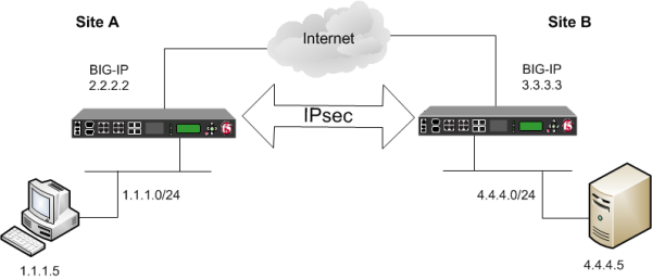
You can configure an IPsec tunnel when you want to secure traffic that traverses a wide area network (WAN), from one BIG-IP ®system to another. By following this procedure, you can create an IPsec tunnel interface that can be used as any other BIG-IP VLAN. When you configure an IPsec tunnel interface, the IKE tunnel mode security associations occur automatically as part of the tunnel negotiation. For the IPsec tunnel interface, only the IPsec Encapsulating Security Protocol (ESP) is supported for the tunnel interface, and IPComp is not available.
Before you begin configuring IPsec, verify that these modules, system objects, and connectivity exist on the BIG-IP® systems in both the local and remote locations:
- BIG-IP Local Traffic Manager
- This module directs traffic securely and efficiently to the appropriate destination on a network.
- Self IP address
- Each BIG-IP system must have at least one self IP address, to be used in specifying the ends of the IPsec tunnel.
- The default VLANs
- These VLANs are named
externalandinternal. - BIG-IP connectivity
- Verify the connectivity between the client or server and its BIG-IP device, and between each BIG-IP device and its gateway. For example, you can use
pingto test this connectivity.
For IPsec, you create a forwarding (IP) type of virtual server to intercept IP traffic and direct it over the tunnel. With a forwarding (IP) virtual server, destination address translation and port translation are disabled.
-
On the Main tab, click Local Traffic > Virtual Servers.
The Virtual Server List screen opens.
-
Click Create.
The New Virtual Server screen opens.
-
In the Name field, type a unique name for the virtual server.
-
From the Type list, select Forwarding (IP).
-
In the Destination Address/Mask field, type a wildcard network address in CIDR format, such as
0.0.0.0/0for IPv4 or::/0for IPv6, to accept any traffic. -
From the Service Port list, select *All Ports.
-
From the Protocol list, select *All Protocols.
-
From the VLAN and Tunnel Traffic list, retain the default selection, All VLANs and Tunnels.
-
Click Finished.
You can create a custom IPsec policy to specify the Interface mode, which allows you to use the IPsec tunnel as a network interface object.
Important: You must perform this task on the BIG-IP systems at both sides of the tunnel.
-
On the Main tab, click Network > IPsec > IPsec Policies.
-
Click the Create button.
The New Policy screen opens.
-
In the Name field, type a unique name for the policy.
-
For the IPsec Protocol setting, retain the default selection, ESP.
-
From the Mode list, select IPsec Interface.
-
Click Finished.
The screen refreshes and displays the new IPsec policy in the list.
-
Repeat this task on the BIG-IP system in the remote location.
The traffic selector you create filters traffic based on the IP addresses you specify and the custom IPsec policy you assign.
Important: You must perform this task on the BIG-IP systems on both sides of the WAN.
-
On the Main tab, click Network > IPsec > Traffic Selectors.
-
Click Create.
The New Traffic Selector screen opens.
-
In the Name field, type a unique name for the traffic selector.
-
For the Source IP Address setting, specify where the application traffic originates, either:
- Click Host and type an IP address.
- Click Network, and in the Address field, type an IP address. This table shows sample source IP addresses for BIG-IP A and BIG-IP B.
System Name Source IP Address BIG-IP A 1.1.1.0/24BIG-IP B 4.4.4.0/24 -
For the Destination IP Address setting, specify where the application traffic is going, either:
- Click Host and type an IP address.
- Click Network, and in the Address field, type an IP address. This table shows sample destination IP addresses for BIG-IP A and BIG-IP B.
System Name Destination IP Address BIG-IP A 4.4.4.0/24BIG-IP B 1.1.1.0/24 -
From the IPsec Policy Name list, select the name of the custom IPsec policy that you created.
-
Click Finished.
The screen refreshes and displays the new IPsec traffic selector in the list.
-
Repeat this task on the BIG-IP system in the remote location.
You can create an IPsec tunnel profile to filter traffic according to the traffic selector you specify.
-
On the Main tab, click Network > Tunnels > Profiles > IPsec > Create.
The New IPsec Profile screen opens.
-
In the Name field, type a unique name for the profile.
-
From the Parent Profile list, select ipsec.
-
Select the Custom check box.
-
From the Traffic Selector list, select the traffic selector you created.
-
Click Finished.
To use this IPsec profile to filter traffic, you must apply it to an IPsec tunnel.
You can create an IPsec interface tunnel to apply an IPsec profile you have created to specify the traffic selector to filter the traffic.
-
On the Main tab, click Network > Tunnels > Tunnel List > Create or Carrier Grade NAT > Tunnels > Create.
The New Tunnel screen opens.
-
In the Name field, type a unique name for the tunnel.
-
From the Profile list, select IPsec.
-
In the Local Address field, type the IP address of the BIG-IP system.
-
From the Remote Address list, select Specify, and type the IP address of the BIG-IP device at the other end of the tunnel.
-
Click Finished.
After you create an IPsec tunnel interface, you can use it just like any other tunnel interface, such as assigning it a self IP address, associating it with route domains, and adding it to virtual servers.
Ensure that you have created an IP tunnel before starting this task.
Self IP addresses can enable the BIG-IP system, and other devices on the network, to route application traffic through the associated tunnel, similar to routing through VLANs and VLAN groups.
Note: If the other side of the tunnel needs to be reachable, make sure the self IP addresses that you assign to both sides of the tunnel are in the same subnet.
-
On the Main tab, click Network > Self IPs.
-
Click Create.
The New Self IP screen opens.
-
In the Name field, type a unique name for the self IP address.
-
In the IP Address field, type the IP address of the tunnel.
The system accepts IPv4 and IPv6 addresses.
Note: This is not the same as the IP address of the tunnel local endpoint.
-
In the Netmask field, type the network mask for the specified IP address.
For example, you can type
255.255.255.0. -
From the VLAN/Tunnel list, select the tunnel with which to associate this self IP address.
-
Click Finished.
The screen refreshes, and displays the new self IP address.
Assigning a self IP to a tunnel ensures that the tunnel appears as a resource for routing traffic.
To direct traffic through the tunnel, add a route for which you specify the tunnel as the resource.